Instruction Manual
D102748X012
DLC3010 Digital Level Controller
Maintenance & Troubleshooting
May 2018
81
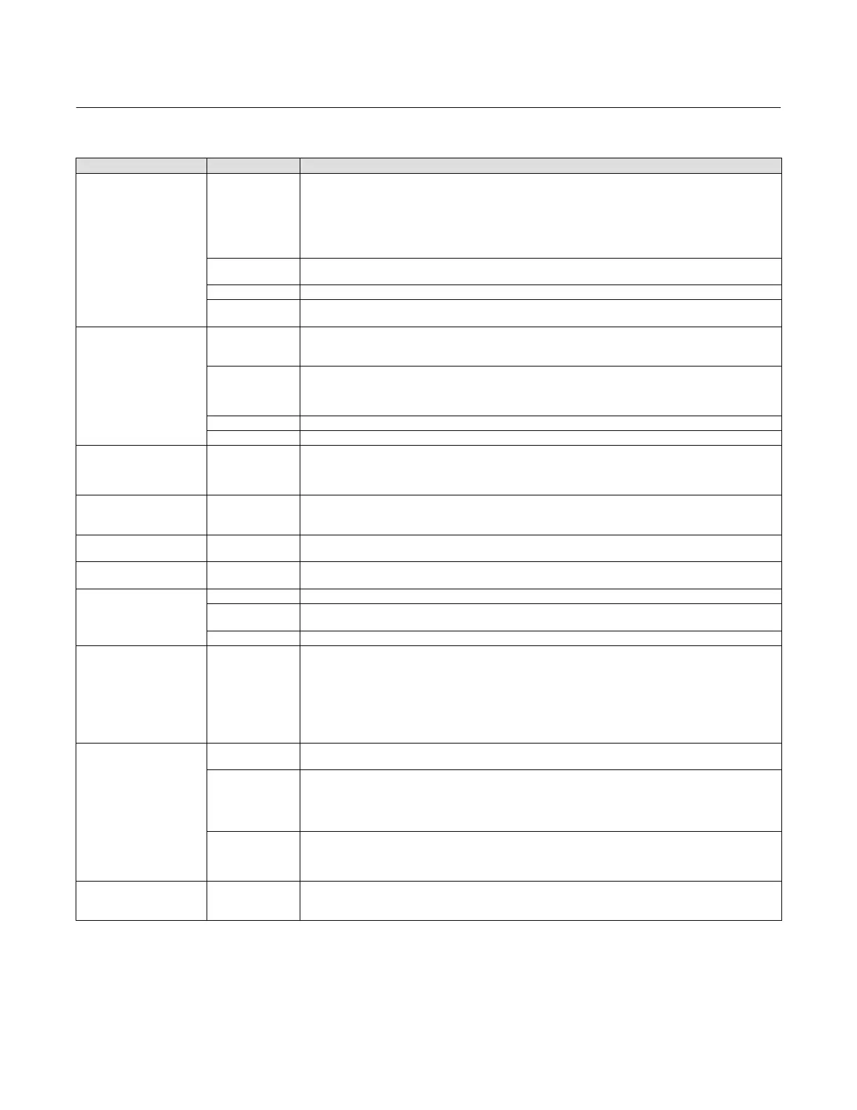
Table 6‐1. Troubleshooting
Symptom Potential Source Corrective Action
Analog Output is within valid
range but Instrument does
not communicate with Field
Communicator
Loop Wiring
1. Check resistance between the power supply and the Field Communicator connection. The net resistance in the
loop must be between 230 and 1100 Ohms for HART communication.
2. Check for adequate voltage to the digital level controller. Refer to figure 2‐10 for requirements. Some models
of battery‐operated field calibrators do not have sufficient compliance voltage to operate a DLC3010 over the
entire output current range.
3. Check for excessive capacitance in the field wiring. (Isolate the instrument from field wiring and try to
communicate locally.)
Terminal Box
4. If the terminal box does not have a 4‐digit date‐code sticker inside the lower lip, it may have developed a high
internal resistance. Try a new terminal box.
Electronics Module 5. Swap the electronics module with a known good part.
Transducer Module
6 If the electronics module and terminal box work on a known good transducer module, replace the old
t.ransducer module.
Output ` 0 mA
Loop Wiring
7. Check for open circuits.
8. Check for proper polarity at the signal terminals.
— See item 2 above.
Terminal Box
9. Check resistance between “Loop+” and “T” terminals of terminal box. If greater than 1.1 Ohm, the internal
sense resistor may be damaged. An external jumper may be added for a temporary repair. Replace terminal box
and avoid applying loop voltage across “T” and “Loop+” for long term solution.
— See item 4 above
Electronics Module — See item 5 above.
Transducer Module — See item 6 above.
Fixed Output ` 3.7 mA
Alarm Condition
(Fail‐low setting)
Connect the Field Communicator and:
10. Select LCD Test (3-4-1-1) to isolate a module failure.
11. Check PV against Hi‐Hi and Lo‐Lo alarm thresholds and PV alarm deadband setting, if these alarms are
enabled.
Fixed Output = 3.8 mA Low Saturation
Connect the Field Communicator and:
12. Check the PV against the upper and lower range values. Check actual process condition and calibration
adjustments.
Fixed Output = 20.5 mA High Saturation
Connect the Field Communicator and:
— see item 12 above.
Fixed Output ` 22.5 mA
Alarm Condition
(Fail‐high setting)
Connect the Field Communicator and:
— see items 10 and 11 above.
Fixed Output > 22.5 mA
Loop Wiring 13. Check for short circuits.
Terminal Box
14. Remove terminal box from the instrument, and apply 24 Volts between Loop+ and Loop- terminals, (with a
series resistance of approximately 1200 Ohms to protect power supply). If any current flows, replace terminal box.
Electronics Module — See item 5 above.
Output is within 4-20 mA
range, but does not track
displayed PV value (e.g.,
a) gain error,
b) low saturation occurs at a
value higher than 3.8 mA,
c) high saturation occurs at a
value lower than 20.5 mA)
Electronics Module
Connect the Field Communicator and:
15. Run Loop diagnostic test (3-4-1-1) [(3-4-1-2) if LCD Configuration is installed]. If the forced output does not
track commands, attempt Scaled D/A Trim procedure (3‐4-3-2-2). If D/A calibration cannot be restored, replace
Electronics Module.
Output Drifting while at
fixed process input.
Sensor
16. Check torque tube spring rate change versus process temperature per figure 1‐2. Use appropriate material for
process
temperature. Pre‐compensate the calibration for target process condition.
Transducer Module
Connect the Field Communicator and:
17. Check Instrument Temperature (3‐2-3) against an independent measurement of DLC3010 temperature.
a) If inaccurate, trim the instrument temperature measurement (3-4-3-1-3) to improve ambient temperature
compensation performance.
b) If Instrument Temperature value is extreme, replace transducer module.
Electronics Module
Connect the Field Communicator and:
18. Run Loop diagnostic test (3-4-1-1) [(3-4-1-2) if LCD Configuration is installed]). Leave instrument in fixed
current mode at 12 mA command and observe analog output variation with ambient temperature. If
drift exceeds
specifications replace electronics
module.
Output Drifting while at
fixed process input.
Configuration Data
Connect the Field Communicator and:
19. Check stored Specific Gravity values (2-2-4-4) against independent measurement of process density. If process
SG has changed from calibration values, correct configuration data to match process
continued

 Loading...


