DVC6000 Digital Valve Controllers
September 2013
B-2
This section includes loop schematics required for
wiring of intrinsically safe installations. It also contains
the approvals nameplates. If you have any questions,
contact your Emerson Process Management sales
office.
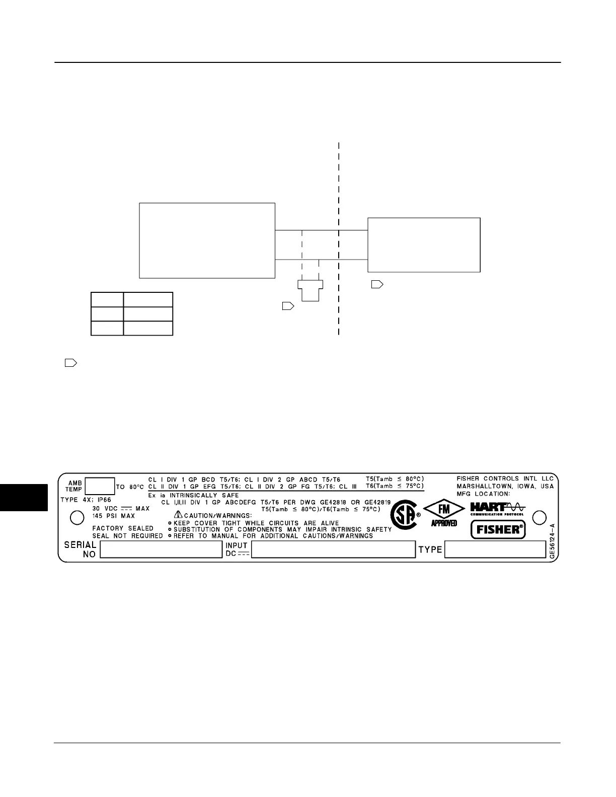
Figure B-1. CSA Loop Schematic for FIELDVUE DVC6010, DVC6020, and DVC6030
GE42818 sheet 2, Rev. E
CSA APPROVED BARRIER
1 NOTE 1, 3, 4, 5, 6
1
NOTE 7
CLASS I, DIV 1, GROUPS A,B,C,D
CLASS II, DIV 1, GROUPS E,F,G
CLASS III
DVC6010, DVC6020, DVC6030
DVC6010S, DVC6020S, DV6030S
Vmax = 30 VDC
Imax = 226 mA
Ci = 5 nF
Li = 0.55 mH
Pi = 1.4 W
NON-HAZARDOUS LOCATION
HAZARDOUS LOCATION
T6 ≤ 75_C
T5 ≤ 80_C
T CODE T (amb)
1 SEE NOTES IN FIGURE B-4
Figure B-2. Typical CSA/FM Nameplate for FIELDVUE DVC6010, DVC6020, DVC6030, and DVC6005
B
 Loading...


