Installation
September 2013
2-31
The voltage available at the instrument is not the voltage measured at the instrument terminals. Once the instrument is
connected, the instrument limits the measured voltage to approximately 9.0 to 10.5 volts.
Obtain filter voltage drop. The measured drop will be different than this value. The measured filter voltage drop
depends upon control system output voltage, the intrinsic safety barrier (if used), and the instrument. See note 3.
HART
FILTER
(if used)
CONTROL
SYSTEM
+
−
COMPLIANCE VOLTAGE
VOLTAGE
AVAILABLE AT
THE
INSTRUMENT
+
−
R
INTRINSIC SAFETY
BARRIER
(if used)
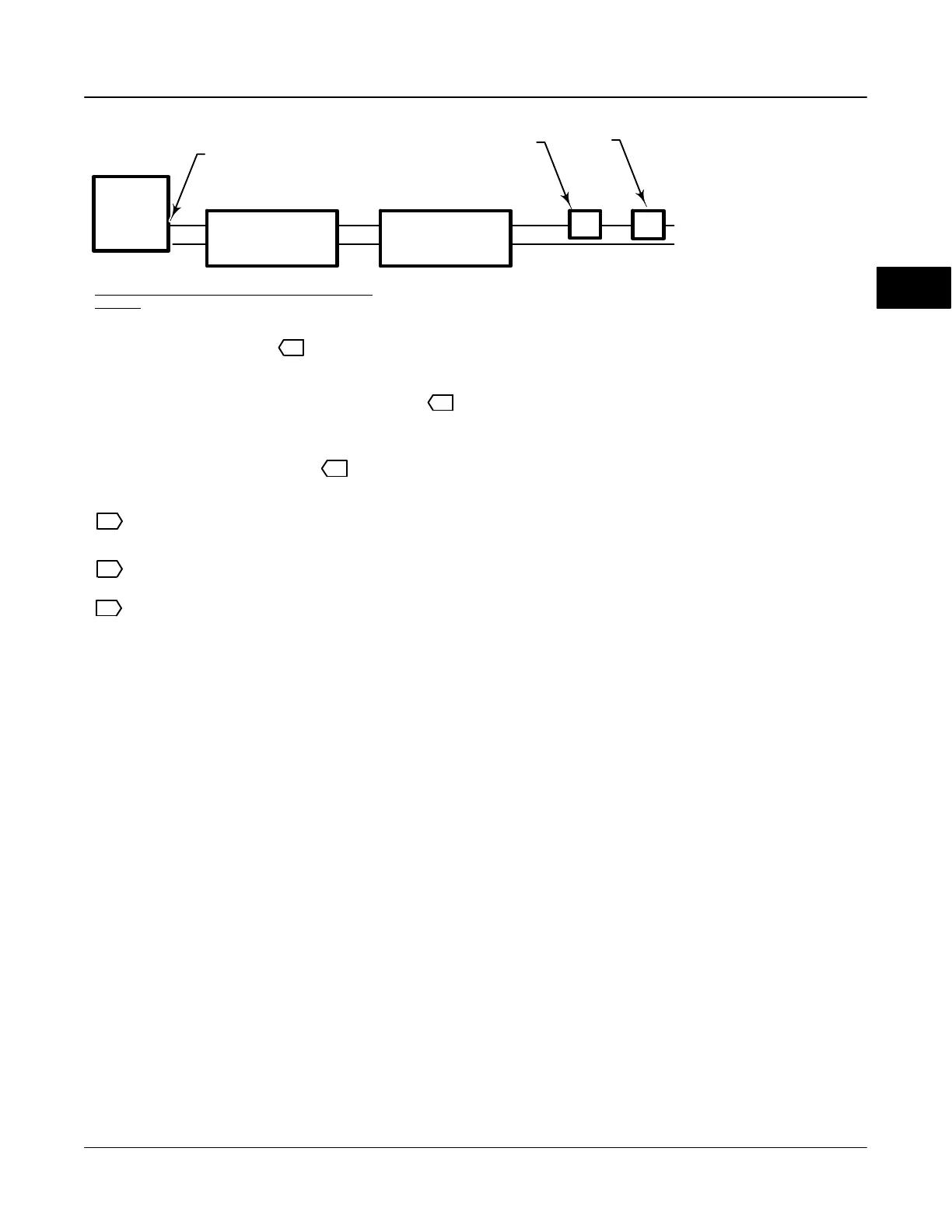
Control system compliance voltage
= Voltage available at the instrument
– Filter voltage drop (if used)
Example Calculation
18.5 volts (at 21.05 mA)
– 2.3 volts (for HF300 filter)
– Intrinsic safety barrier resistance (if used) x maximum loop current – 2.55 volts (121 ohms x 0.02105 amps)
TOTAL LOOP
CABLE RESISTANCE
– Total loop cable resistance x maximum loop
current
– 1.01 volts (48 ohms x 0.02105 amps for
1000 feet of Belden 9501 cable)
= 15.19 volts, available—if safety barrier (2.55 volts)
is not used
1
3
NOTES:
1
2
Calculate Voltage Available at the Instrument as
follows:
THUM ADAPTER
(IF USED)
– Smart Wireless THUM adapter voltage drop (if used) 2
The voltage drop of the THUM adapter is linear from 2.25 volts at 3.5 mA to 1.2 volts at 25 mA.
3
Figure 2-25. Determining Voltage Available at the Instrument
Voltage Available
The voltage available at the DVC6000 digital valve
controller must be at least 11 volts DC. The voltage
available at the instrument is not the actual voltage
measured at the instrument when the instrument is
connected. The voltage measured at the instrument is
limited by the instrument and is typically less than the
voltage available.
As shown in figure 2-25, the voltage available at the
instrument depends upon:
the control system compliance voltage
if a filter, wireless THUM adapter, or intrinsic
safety barrier is used, and
the wire type and length.
The control system compliance voltage is the
maximum voltage at the control system output
terminals at which the control system can produce
maximum loop current.
The voltage available at the instrument may be
calculated from the following equation:
Voltage Available = [Control System Compliance
Voltage (at maximum current)] − [filter voltage drop (if
a HART filter is used)] − [total cable resistance
maximum current] − [barrier resistance x maximum
current].
The calculated voltage available should be greater
than or equal to 11 volts DC.
Table 2-1 lists the resistance of some typical cables.
The following example shows how to calculate the
voltage available for a Honeywell TDC2000 control
system with a HF340 HART filter, and 1000 feet of
Belden
9501 cable:
Voltage available = [18.5 volts (at 21.05 mA)] − [2.3
volts] − [48 ohms 0.02105 amps]
Voltage available = [18.5] − [2.3] − [1.01]
Voltage available = 15.19 volts
2
 Loading...


