DVC6000 Digital Valve Controllers
September 2013
2-32
Table 2-1. Cable Characteristics
Cable Type
Capacitance
(1)
pF/Ft
Capacitance
(1)
pF/m
Resistance
(2)
Ohms/ft
Resistance
(2)
Ohms/m
BS5308/1, 0.5 sq mm 61.0 200 0.022 0.074
BS5308/1, 1.0 sq mm 61.0 200 0.012 0.037
BS5308/1, 1.5 sq mm 61.0 200 0.008 0.025
BS5308/2, 0.5 sq mm 121.9 400 0.022 0.074
BS5308/2, 0.75 sq mm 121.9 400 0.016 0.053
BS5308/2, 1.5 sq mm 121.9 400 0.008 0.025
BELDEN 8303, 22 awg 63.0 206.7 0.030 0.098
BELDEN 8441, 22 awg 83.2 273 0.030 0.098
BELDEN 8767, 22 awg 76.8 252 0.030 0.098
BELDEN 8777, 22 awg 54.9 180 0.030 0.098
BELDEN 9501, 24 awg 50.0 164 0.048 0.157
BELDEN 9680, 24 awg 27.5 90.2 0.048 0.157
BELDEN 9729, 24 awg 22.1 72.5 0.048 0.157
BELDEN 9773, 18 awg 54.9 180 0.012 0.042
BELDEN 9829, 24 awg 27.1 88.9 0.048 0.157
BELDEN 9873, 20 awg 54.9 180 0.020 0.069
1. The capacitance values represent capacitance from one conductor to all other conductors and shield. This is the appropriate value to use in the cable length calculations.
2. The resistance values include both wires of the twisted pair.
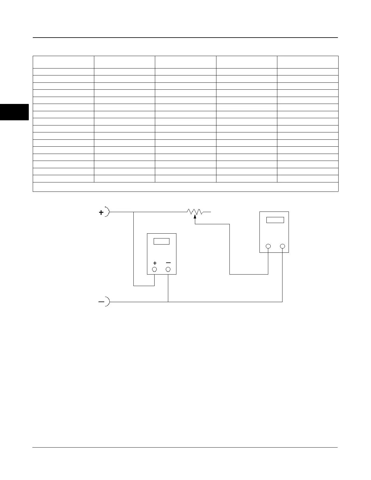
CIRCUIT
UNDER
TEST
VOLTMETER
MILLIAMMETER
1 kW POTENTIOMETER
A6192-1/IL
Figure 2-26. Voltage Test Schematic
Compliance Voltage
If the compliance voltage of the control system is not
known, perform the following compliance voltage test.
1. Disconnect the field wiring from the control system
and connect equipment as shown in figure 2-26 to the
control system terminals.
2. Set the control system to provide maximum output
current.
3. Increase the resistance of the 1 kW potentiometer,
shown in figure 2-26, until the current observed on the
milliammeter begins to drop quickly.
4. Record the voltage shown on the voltmeter. This is
the control system compliance voltage.
For specific parameter information relating to your
control system, contact your Emerson Process
Management sales office.
2
 Loading...


