DVC6000f Series
March 2006
2-24
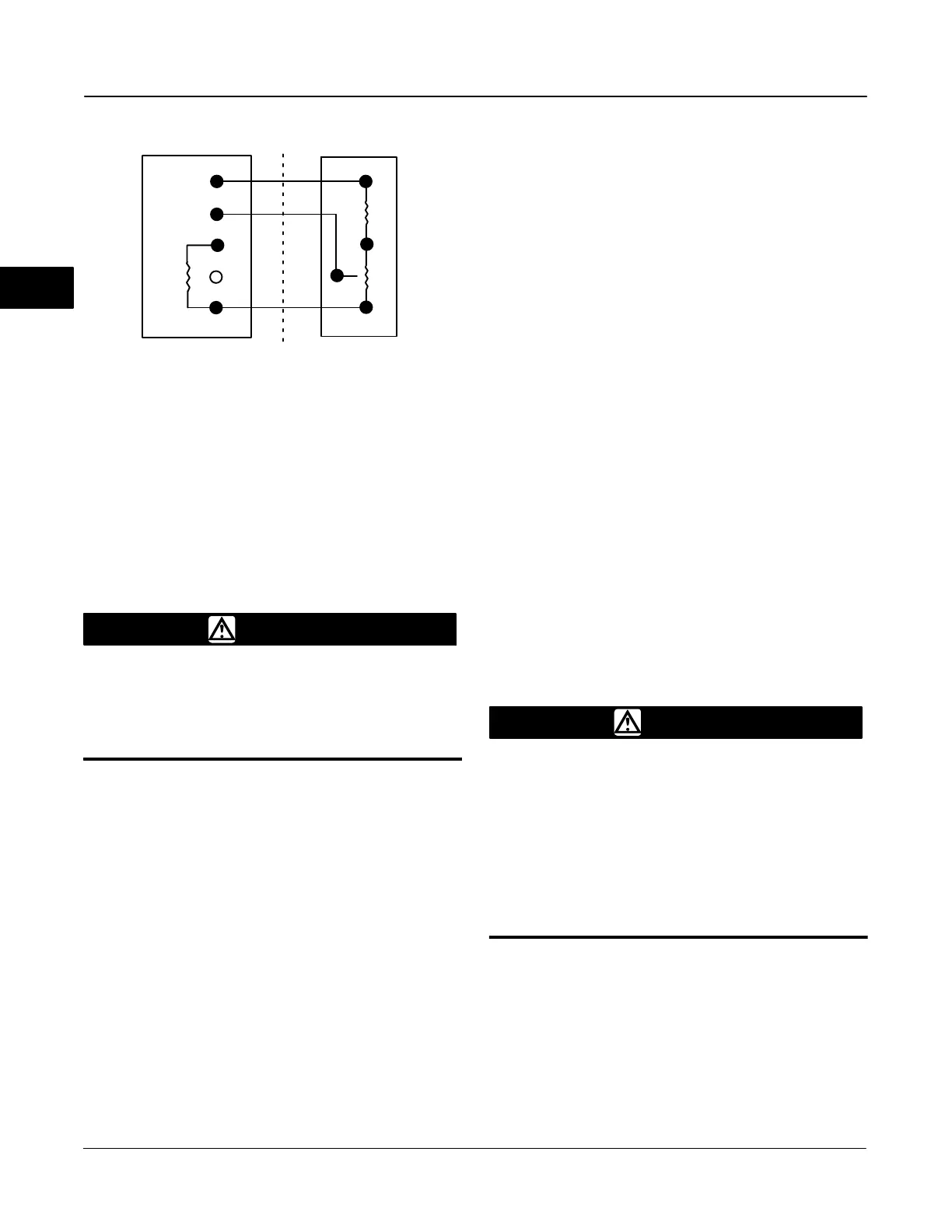
Figure 2-21. Terminal Details for Connecting a DVC6005f
Base Unit and a Three-Resistor Series
3
1
30kW
(R
2
)
(R1)
2
"
(R
pot
)
BASE UNIT TERMINATION BOX
(DVC6005)
3RD PARTY FEEDBACK ELEMENT
(WITH R
1
, R
2
and R
pot
)
The resistance of R
2
is 4 times less than
R
pot(max)
.
WARNING
To avoid personal injury or property
damage from an uncontrolled process
ensure that the R1 resistor is properly
insulated before installing it in the
terminal box.
1. On the base unit, remove the feedback
connections terminal box cap (see figure 2-15).
2. If necessary, install conduit between the base unit
and the remote travel sensor following applicable local
and national electrical codes. Route the 3-conductor
shielded cable between the two units (refer to figure
2-21).
3. Install the fixed resistor (R1) across the unlabeled
bottom Terminal and Terminal #1. The bottom terminal
does not have a screw. The screw on the 30 kOhm
terminal can be used. R1 must be properly insulated
when installed in the terminal box to prevent personal
injury or property damage.
4. Connect one wire of the 3-conductor shielded cable
between the unlabeled bottom Terminal on the base
unit and an end-lead on the external potentiometer
(Rpot).
5. Connect the second wire of the 3-conductor
shielded cable between the middle lead (wiper) of the
external potentiometer (R
pot
) and Terminal #2 on the
base unit.
6. Connect the third wire of the 3-conductor shielded
cable between a lead on (R
2
) and Terminal #3 of the
base unit.
7. Connect the available end-lead on the
potentiometer (R
pot
) with the available lead on fixed
resistor (R
2
).
8. Connect the cable shield or drain wire to the
ground screw in the feedback connections terminal
box of the base unit. Do not connect the shield or
drain wire to any lead on the three-resistor series.
9. Replace and tighten the base unit cover.
Example: Using a linear potentiometer rated at 400
Ohms/inch on an actuator with 16” of travel.
R
pot(max)
is 400 Ohms/in x 16” = 6.4 kOhm
R
1
= 6.4 kOhm x 4.25 = 27.2 kOhm
R
2
= 6.4 kOhm / 4 = 1.6 kOhm
Communication Connections
WARNING
Personal injury or property damage
caused by fire or explosion may occur
if this connection is attempted in a
potentially explosive atmosphere or in
an area that has been classified as
hazardous. Confirm that area
classification and atmosphere
conditions permit the safe removal of
the terminal box cap before
proceeding.
A FOUNDATION fieldbus communicating device, such
as a 375 Field Communicator or a personal computer
running AMS ValveLink Software, interfaces with the
DVC6000f Series digital valve controller from any
wiring termination point in the segment. If you choose
to connect the fieldbus communicating device directly
to the instrument, attach the device to the LOCAL
connections inside the terminal box to provide local
communications with the instrument.
2
 Loading...


