Safe Use Instructions – Emerson FloBoss 104
Part D301733X012
February 2018
www.Emerson.com/RemoteAutomation 5
Default values for all parameters exist in the firmware of
the FloBoss. If the default is acceptable for your
application, it can be left as it is. Perform adjustments to
the FloBoss through the configuration software. Refer to
the ROCLINK 800 Configuration Software User Manual (Part
D301159X012).
8. The calibration routines support 5-point calibration,
with the three mid-points calibrated in any order. The low-
end or zero reading is calibrated first, followed by the
high-end or full-scale reading. The three mid-points can
be calibrated next, if desired. The diagnostic analog
inputs—logic voltage (E1), battery voltage (E2), and
board/battery temperature (E5)—are not designed to be
calibrated.
With the optional I/O termination points installed, the
Analog Input can be calibrated using ROCLINK 800
software.
The built-in inputs that are supported with the 5-point
calibration are:
▪ Differential pressure located at AI Point A1.
▪ Static pressure located at AI Point A2.
▪ RTD temperature located at AI Point A3.
These inputs are assigned to the first three Analog Input
points. The calibration procedure for these inputs is
described in the ROCLINK 800 Configuration Software User
Manual (Part D301159X012).
9. To troubleshoot problems with the FloBoss 104,
identify whether the problem is with the configuration or
the hardware. Check the configuration in ROCLINK 800
software to identify any incorrect settings. Inspect the
hardware for damage. Inspect the termination boards for
connection location errors.
If you are experiencing problems with the FloBoss 104 that
appear to be software related, try resetting the FloBoss
with a warm start, a cold start, or a jumper reset.
If you are experiencing problems that appear to be
hardware-related, verify the wiring. If you still experience
problems, contact your local sales office for return
authorization.
During operation, the FloBoss 104 can be monitored (to
view or retrieve current and historical data) either locally
or remotely. Local monitoring is accomplished either by
viewing the LCD panel detailed in Section 2, or by using
ROCLINK 800 software on a PC connected through the LOI
port. Remote monitoring is performed through Comm 1
or Comm 2 of the FloBoss using ROCLINK 800 software, or
host system. Refer to Figure 8 for the communication
terminations.
10. To remove the FloBoss 104 from operation.
disconnect power from the unit and then remove all
external wiring connections. Remove the gas lines. Finally
remove the FloBoss housing from the pipestand or orifice
plate. The FloBoss may be placed in a box for
transportation.
DANGER
Take care when removing gas lines from the FB104.
Use one wrench to prevent the sensor connector from
moving, and use a second wrench to disconnect the
gas line. Allowing the sensor to rotate will damage the
internal wiring.
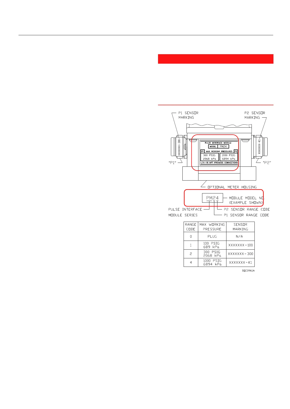
Figure 7. FB104 Pulse Interface Housing
When connecting gas pressure lines to the optional
Pulse Interface module, note the maximum working
pressure limits to the individual P1 and P2 sensors
based on the model number of the module. For
example, Figure 7 shows a model PM24 module with
its P1 (300 PSIG/2068 kPa) and P2 (1000 PSIG/6894
kPa) sensor ranges.

 Loading...


