9
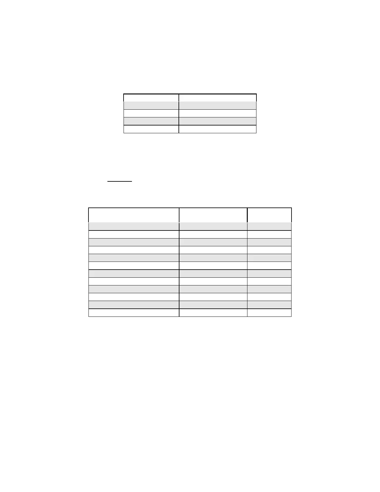
2.5.5.3 Digital / Relay Outputs
There are four (4) Form A relay outputs rated 125 Vac, 0.5 A on the Electronic
bypass control board.
Terminal No. Description
TB1-1 & TB1-2 Power On
TB1-3 & TB1-4 Fault
TB1-5 & TB1-6 Damper actuator
TB1-7 & TB1-8 Automatic mode selected
2.5.5.4 Internal Control Wire Connections
There are factory connections between the Electronic bypass control board and
the Affinity inverter. These connections are made at the factory and are for
reference only. Do not change this wiring as it will cause the Electronic bypass to
operate improperly or not at all.
Electronic bypass control
Board
FPCBA
Wire
number
J11 – 1 Motor overload relay 12
J11 – 2 41 11
J11 – 3 11 16
J11 – 4 29 10
J11 – 5 N/C N/A
J11 – 6 26 8
J11 – 7 25 9
J10 - 1 Input Contactor 5
J10 – 2 Bypass Contactor 4
J10 - 3 Output Contactor 3
J10 - 4 115 Vac (Neutral) 2
J10 - 5 115 Vac (Hot) 1