13
Electronic Bypass Control Functions
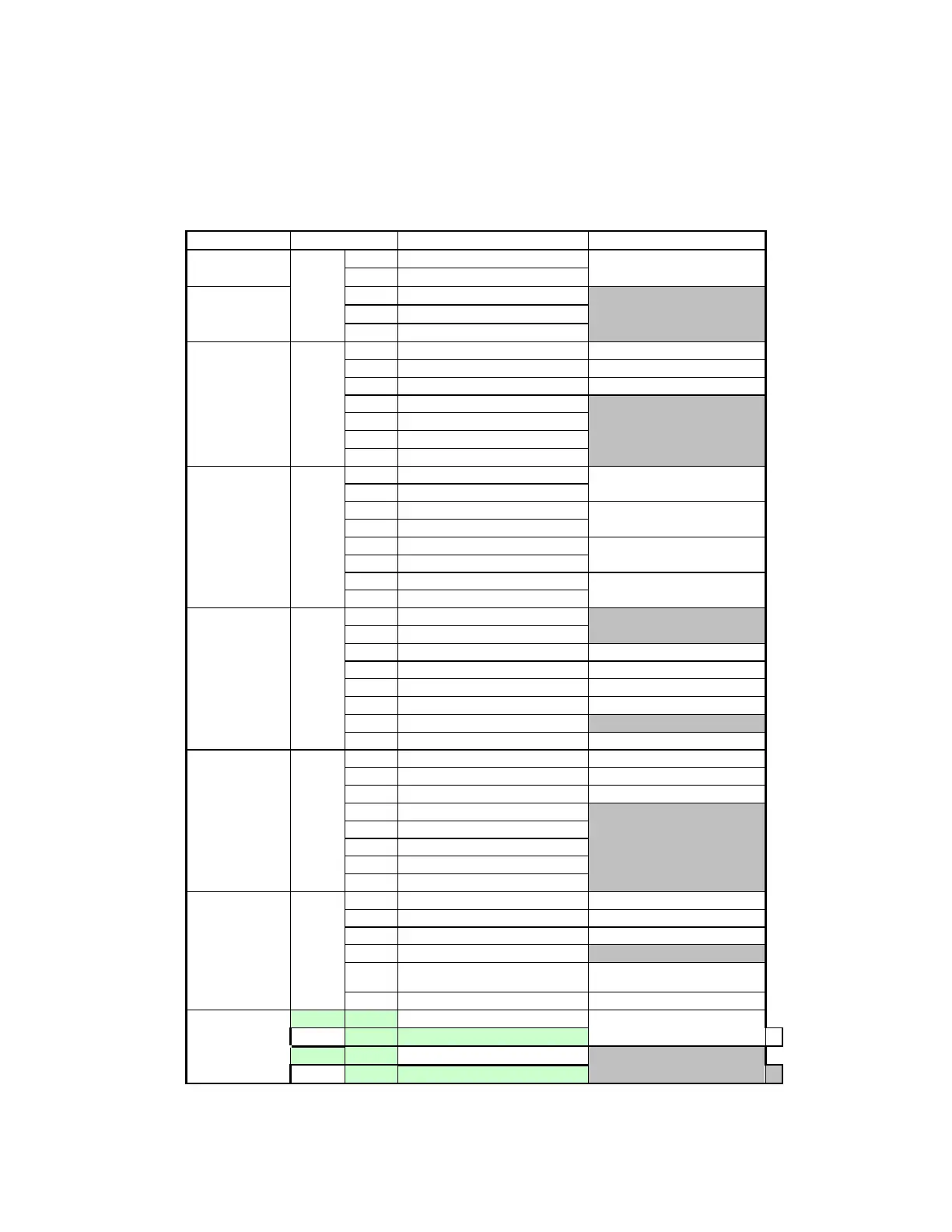
TYPE LOCATION DESCRIPTION SIGNAL LEVEL/RATING
Input Power
J10
5 120 Vac single phase (neutral)
120 Vac Single Phase
4 120 Vac single phase (hot)
Contactor
Outputs
1 Input Contactor
2 Bypass Contactor
3 Output Contactor
VFD
Connections
J11
1 Motor Overload Input 24 Vdc upon overload
2 Drive Fault Input 24 Vdc upon fault
3 24 Vdc Common to VFD Drive common
4 Frequency Local/Remote
5 N/A
6 Run Command
7 VFD Reset
Relay Outputs TB1
1 Power On
Closes when power is
applied
2 Power On
3 Fault
Closes upon a fault condition
4 Fault
5 Damper
Activates Damper Solenoid
6 Damper
7 Auto
Closes when placed in Auto
8 Auto
Digital Inputs TB2
1 Safety Tie 1
2 Safety Tie 2
3 Safety NC Contact
4 Customer Reset NO Contact
5 Auto Run NO Contact
6 Fire NC Contact
7 Fused 24 Vdc
8 24 Vdc Common Digital Input Common
Digital Inputs TB3
1 Remote Bypass Remote Bypass Command
2 Remote VFD Remote VFD Command
3 Damper Feedback Feedback from end switch
4 Fireman’s Override
5 N/A
6 N/A
7 N/A
8 Positive logic ON
Power Supplies TB4
24 Vdc Common Digital Input Common
24 Vdc Common Digital Input Common
24 Vdc Common Digital Input Common
N/A
Contactor Supply 115 Vac Tie 1
115 Vac Tie 2
115 Vac to Contactors
115 Vac Tie (Hot) 115 Vac to Contactors
Analog Input
Affinity 7 External Speed Reference
4-20 mA
HSK T2
Affinity 11 Speed Reference Common
HSK
T1