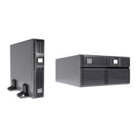
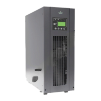
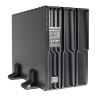
Diagram 3: 6000R(L)/10000R(L) rear panel I Diagram 4: Input/Output terminal
(without parallel function) for rack rear panel I
Diagram 5: 6000R(L)/10000R(L) rear panel II Diagram 6: Input/Output terminal
(with parallel function) for rack rear panel II
Diagram 7: 6000R/10000R battery pack rear panel
1. RS-232 communication port
2. USB communication port
3. Emergency power off function connector (EPO connector)
4. Share current port (only available for parallel model)
5. Parallel port (only available for parallel model)
6. Intelligent slot
7. Cooling fan
8. External maintenance bypass switch port
9. Maintenance bypass switch
10. Input circuit breaker
11. Output receptacles: connect to mission-critical loads
12. Output circuit breaker for receptacles
 Loading...

