EasyManua.ls Logo

Emerson Micro Motion 2500 - Page 204

Emerson Micro Motion 2500
282 pages
Print Icon
To Next Page IconTo Next Page
To Previous Page IconTo Previous Page
Loading...
194 Micro Motion Series 1000 and Series 2000 Transmitters
Menu Flowcharts – Model 2500 CIO Transmitters
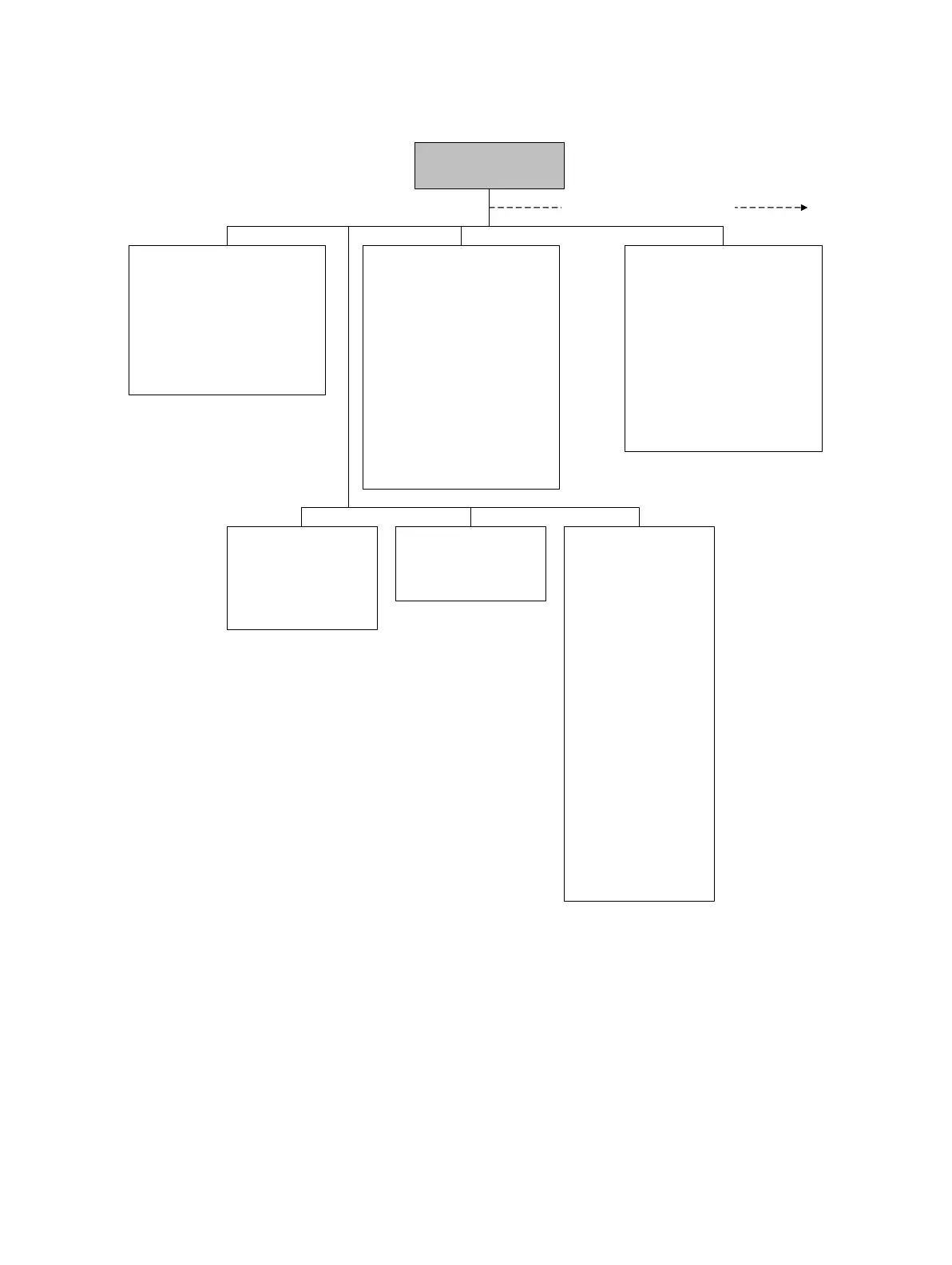
Figure D-3 ProLink II configuration menu continued
Analog output
Primary/secondary output
• PV/SV is
• Lower range value
• Upper range value
• AO cutoff
• AO added damp
•LSL
•USL
•Min span
• AO fault action
• AO fault level
• Last measured value timeout
Frequency
• Tertiary variable
• Scaling method
• Freq factor
• Rate factor
• Pulses per unit
• Units per pulse
• Freq pulse width
• Last measured value timeout
• Freq fault action
• Freq output mode
• Freq output polarity
Discrete input
• Assignment
•Polarity
ProLink >
Configuration
Channel
Channel B
• Type assignment
• Power type
Channel C
• Type assignment
• Power type
Additional configuration options
Discrete output
Discrete output 1/2
• DO1/2 assignment
• DO1/2 polarity
• DO1/2 fault action
Sensor simulation
• Enable/disable
Mass flow
•Wave form
• Fixed value
•Period
• Minimum
•Maximum
Density
•Wave form
• Fixed value
•Period
• Minimum
•Maximum
Temperature
•Wave form
• Fixed value
•Period
• Minimum
•Maximum

Table of Contents