Safety
Information
Product
information
Mechanical
Installation
Electrical
installation
Getting
started
Basic
parameters
Running the
motor
Optimization
SMARTCARD
operation
Onboard
PLC
Advanced
parameters
Technical
data
Diagnostics
UL
information
Mentor MP User Guide 19
Issue: 3 www.controltechniques.com
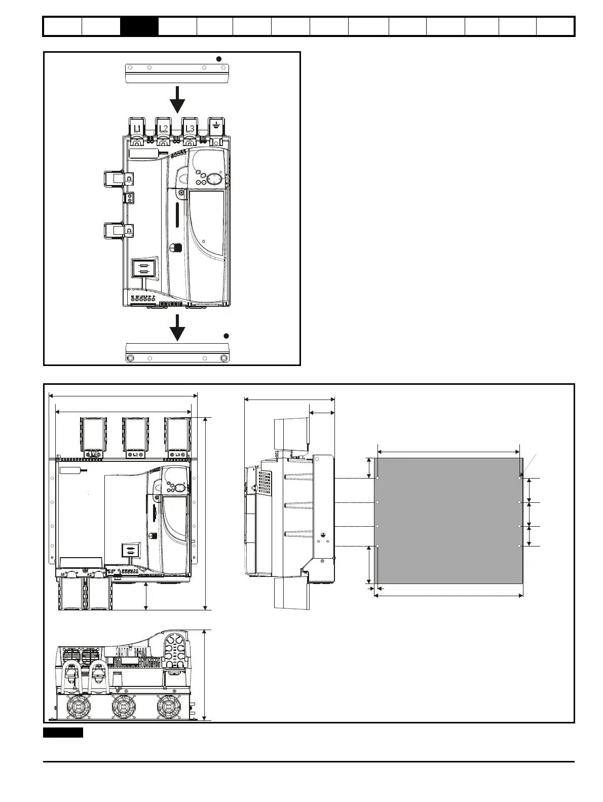
Figure 3-7 Installing the mounting feet bracket on size 1 drives
Figure 3-8 Overall size 2A / 2B dimensions
With the SMARTCARD installed to the drive, the depth measurement increases by 7.6mm (0.30 in).
453mm (17.84in)
495mm (19.49in)
640mm
(25.20in)
85mm
(3.35in)
301mm (11.85in)
68mm
(2.68in)
126mm
(4.96in)
80mm
(3.15in)
80mm
(3.15in)
65mm
(2.56in)
8 holes to
suit M8
302mm
(11.89in)
93mm
(3.66in)
The bottom mounting bracket (1) should be installed to the back plate first
with the screws fully tightened. The drive should then be lowered onto the
bracket and slotted in. The top mounting bracket (2) should then be slotted
into the drive and the top holes marked for mounting (380mm [14.96 in]
from the centre of the holes on the bottom mounting bracket). Once the
holes have been drilled, fix the top mounting bracket accordingly and
tighten the screws.
It is not necessary to tighten the bottom mounting brackets with the drive in
place. The brackets are designed to clamp the drive heatsink against the
back plate.