Safety
Information
Product
information
Mechanical
Installation
Electrical
installation
Getting
started
Basic
parameters
Running the
motor
Optimization
SMARTCARD
operation
Onboard
PLC
Advanced
parameters
Technical
data
Diagnostics
UL
information
30 Mentor MP User Guide
www.controltechniques.com Issue: 3
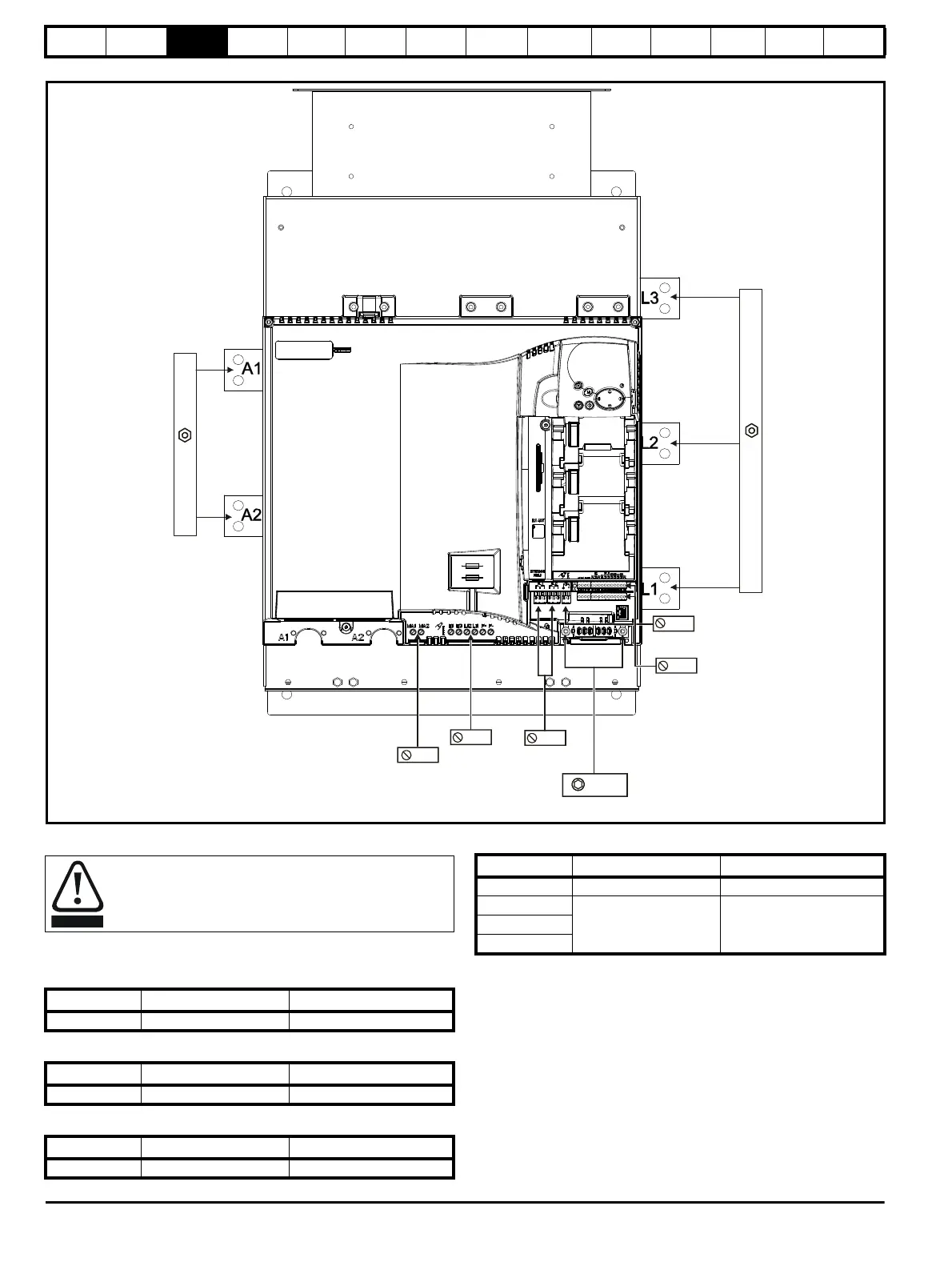
Figure 3-21 Location of the power and ground terminals on size 2C and 2D drives
3.9.2 Terminal sizes and torque settings
3.9.3 Torque settings
Table 3-1 Drive control, status relay and encoder terminal data
Table 3-2 Drive auxiliary and machine armature terminal data
Table 3-3 Drive power stage terminals on size 1 drives
Table 3-4 Drive power stage terminals on size 2 drives
Size 2C / 2D:
M12 nut 19mm AF
5mm
Machine
terminals
5mm
Auxiliary
connections
Relay
connections
Size 2C / 2D:
M12 nut 19mm AF
AC Input
DC Output
To avoid a fire hazard and maintain validity of the UL listing,
adhere to the specified tightening torques for the power and
ground terminals. Refer to the following tables.
Model Connection type Torque setting
All Plug-in terminal block 0.5 Nm 0.4 lb ft
Model Connection type Torque setting
All Terminal block 0.5 Nm 0.4 lb ft
Model Connection type Torque setting
All M8 stud 10 Nm 7.4 lb ft
Model Connection type Torque setting
Size 2A M10 stud 15 Nm (11.06 lb ft)
Size 2B
M12 stud 30 Nm (22.12 Ib ft)Size 2C
Size 2D