14 • MultiFlex I/O Board Operator’s Guide 026-1704 Rev 6 06-APR-10
4 I/O Board Input and
Output Setup
4.1. The Inputs
The inputs on a MultiFlex board are compat-
ible with a wide range of analog and digital sen-
sors and transducers. In general, the inputs are
capable of reading analog voltage signals in the
range of 0V to +7VDC and dry-contact (no out-
side voltage) digital sensors and switches.
The specific types of input devices that must
be used with MultiFlex is largely dependent on
the site controller MultiFlex is connected to;
refer to the site controller’s user’s manual for a
full list of compatible sensors and specific sen-
sor wiring instructions.
4.1.1. Connecting Sensors to Input
Boards
Wiring a sensor to the input points on a Mul-
tiFlex board requires three steps:
1. Connect the sensor’s signal wires to the two
terminals of an input point.
2. Set the input type dip switch that corre-
sponds to the point being connected.
3. If necessary, connect the sensor to one of the
5V or 12V power terminals.
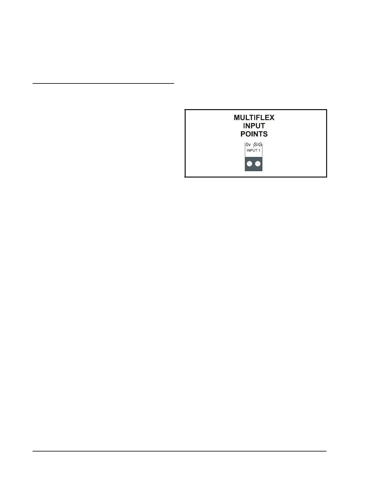
4.1.1.1. Wiring
An input point on a MultiFlex board consists
of two terminals, as shown in Figure 4-1. One of
these terminals, labeled “SIG,” reads the signal
from the sensor, while the other, labeled “0v” is
where the sensor’s ground and/or cable shield
wire is connected.
4.1.1.2. Input Wiring When Replacing
16AI or CIO/8IO Boards With
MultiFlex
If the MultiFlex you are installing is replac-
ing an existing 16AI, CIO, or 8IO, you will not
be able to simply unplug the input connectors
from the old board and plug them into the Multi-
Flex. Doing so will cause the inputs to be
reversed and the polarity to be swapped for
points 1 through 8.
You must either re-wire points 1 through 8 to
the proper place on the MultiFlex board, or
obtain Multiflex input adapter cables (P/N 335-
2301), as shown in Figure 4-2. For each 8-ter-
minal connector plugged into points 1-4 and 5-8,
Figure 4-1 - Input Board Points