10 Chapter 2 Installation Instruction
NetSure 211 C45 Embedded Power Supply System User Manual
Connection method:
Peel one end of the signal cable and insert the end to OT connection terminal or UT terminal with M4 installation bolt.
Carry out the insulation process to the connection terminals and cable ends. Insert the connection terminals into the
dry contacts. Fasten the connection by tightening the screw on the terminal block.
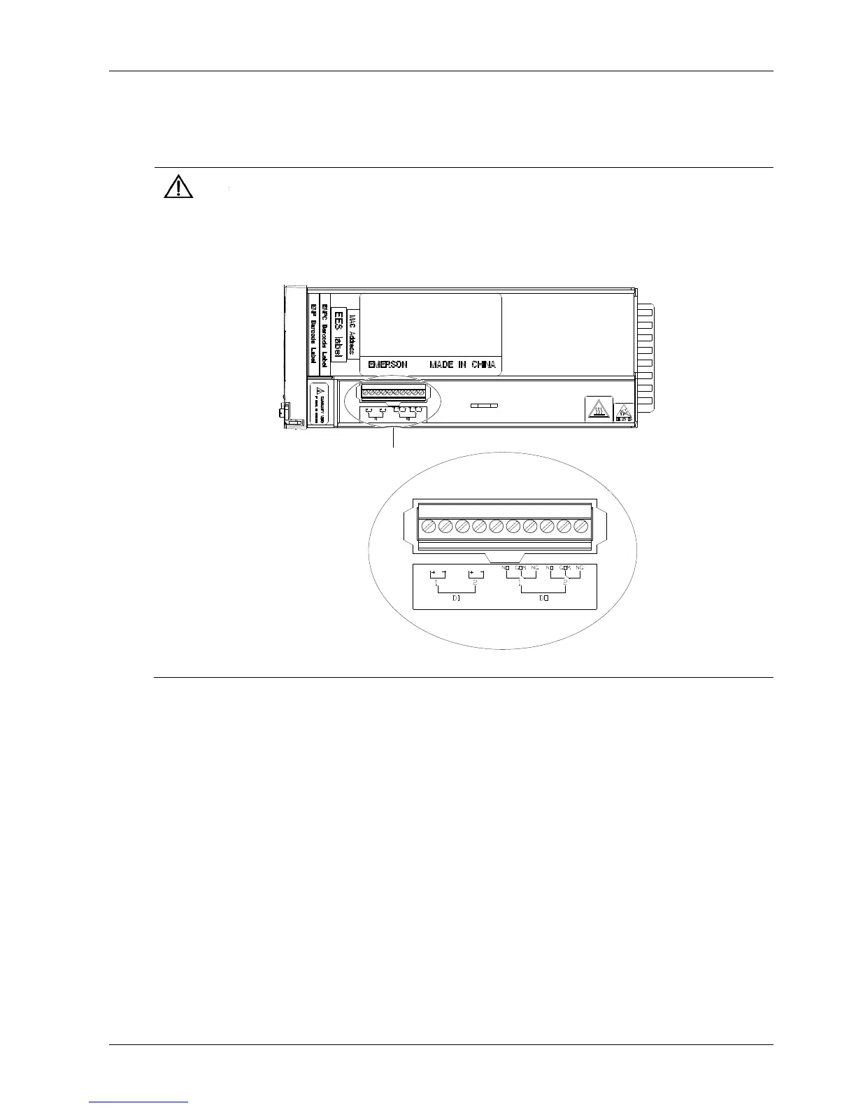
The output dry contacts are normally open by default. If users want to use normally-closed contacts, they need to pull out the
monitoring module and change the NO-COM connections to NC-COM connections at the dry contact socket. The position and
definition of the dry contact socket is shown in the following figure.
The default associations of the relays are: critical alarm associating with DO1, and major alarm associating with DO2.

 Loading...