Quick Panel Operator User Manual Section 4
GFK-2847AA Jan 2023
Pre-installation Checks 48
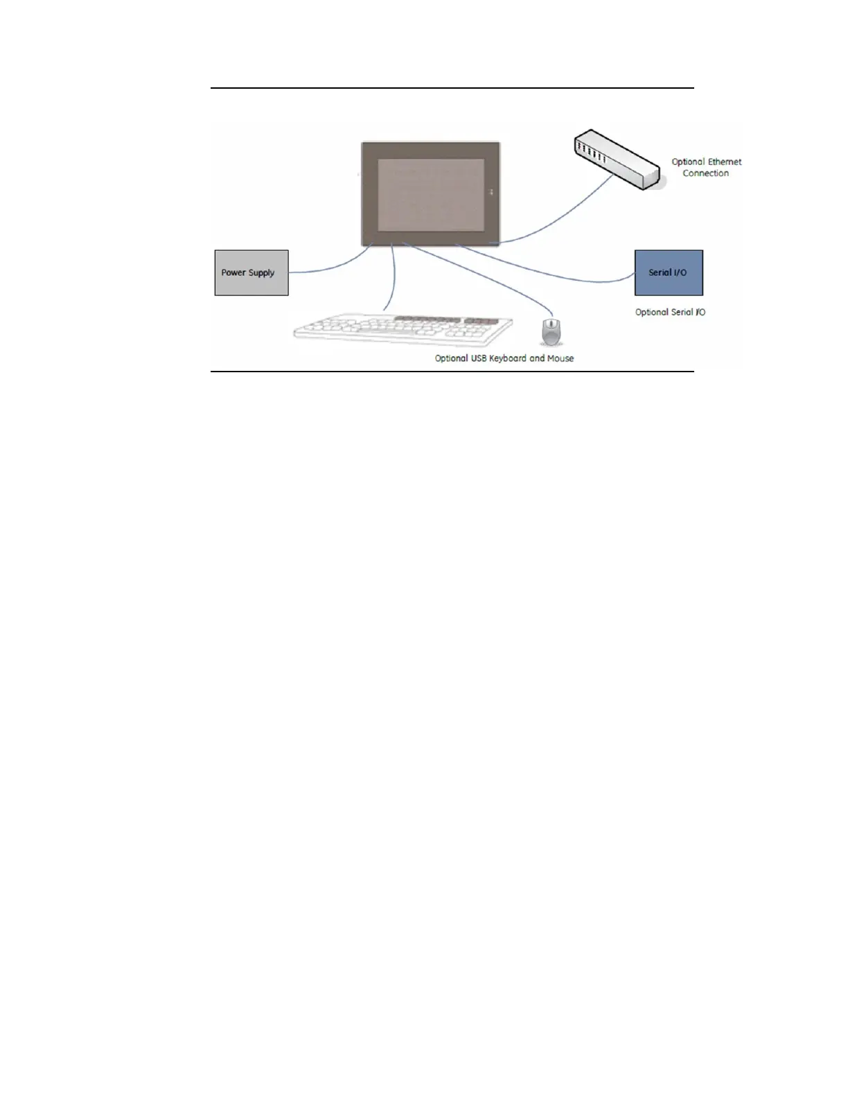
Figure 46: Basic Setup Diagram
4.3 Initial Start-up
You will need the following:
•
Safety Extra Low Voltage (SELV) and Limited Energy Circuit or SELV
and Class 2 dc power supply.
•
The power terminal block is supplied with the product. For voltage
and requirements, refer to the Input Power specifications for each
product in Section 1.1, Specifications.
•
The mating power terminal block supports stranded 30 to 14 AWG
(0.05 to 2.00 mm2) wires. The user calculates proper gauge wiring for
current carrying capacity and loss according to local regulations.
•
At a minimum, the cable must be rated for 75°C (167°F), or more.
•
USB-compatible keyboard (optional)
•
USB-compatible mouse (optional)
4.3.1 Connecting Input Power
To connect input power:
1.
Verify that the power cable is not energized.
2.
Loosen the screw clamps on the mating power connector.
3.
Strip the insulation from the power cables.
4.
Secure the power cable to the mating connector, noting polarity,
and tighten the screw clamps. The torque for the attaching
screws is 0.3 Nm (2.66 in-lb.).
 Loading...