Reference Manual
00809-0100-4690, Rev FC
June 2011
4-3
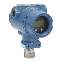
Rosemount 2088 and 2090
Figure 4-1. Transmitter Data
Flow with Calibration Options
NOTE
The 2088/2090 has been carefully calibrated at the factory. Trimming adjusts
the position of the factory characterization curve. It is possible to degrade
performance of the transmitter if any trim is done improperly or with
inaccurate equipment.
Determining Calibration
Frequency
Calibration frequency can vary greatly depending on the application,
performance requirements, and process conditions. Use the following
procedure to determine calibration frequency that meets the needs of your
application.
1. Determine the performance required for your application.
2. Determine the operating conditions.
3. Calculate the Total Probable Error (TPE).
4. Calculate the stability per month.
5. Calculate the calibration frequency.
Transmitter Electronics Module
Microprocessor
Digital PV
Sensor
Input Device
Output Device
20.00 mA
2088s:PT-4763
1 ➡Device Setup
Online
2PV100.00 inH2O
3AO20.00 mA
4LRV0.00 inH2O
5URV100.00 inH2O
Transmitter Ranged 0 to 100 inH
2
O
Input
Pressure
Sensor
Signal
Analog Output
Field
Communicator
NOTE
Value on PV line should equal
the input pressure. Value on
AO line should equal the
output device reading.
 Loading...