EasyManuals Logo

Emerson Rosemount 470XA User Manual

Emerson Rosemount 470XA
140 pages
To Next Page IconTo Next Page
To Previous Page IconTo Previous Page
Page #17 background imageLoading...
Page #17 background image
2.2  Interior
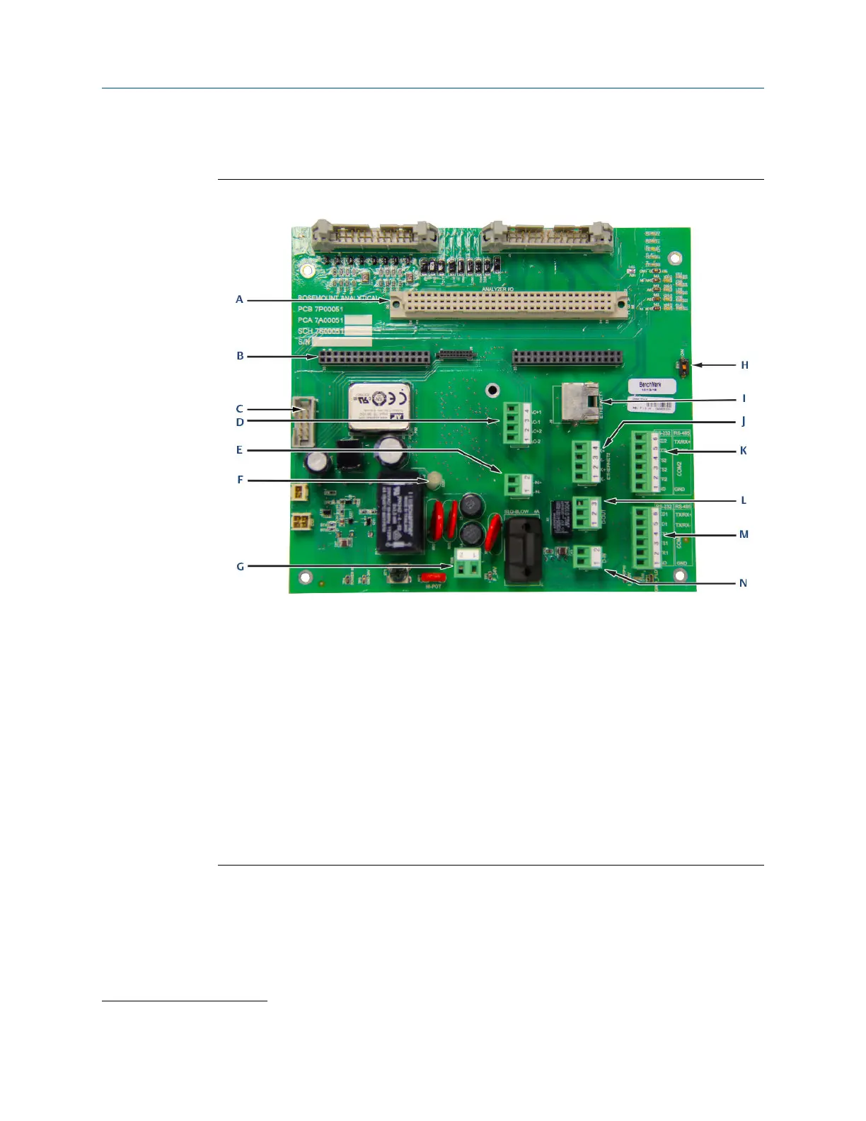
Figure 2-6: Backplane board
A. ANA: Analyzer board
B. CPU: Central processing unit board
C. J8: Local operator interface (LOI) connector
D. TB10: Analog outputs (two)
E. TB2: Analog input
F. LED: LED light
(1)
G. TB8: 24 Vdc power
H. SW1: DHCP switch
I. RJ45: Plug-in Ethernet port
J. TB5: Wired Ethernet port
K. TB9: Communication 2 port
L. TB3: Digital output
M. TB4: Communication 1 port
N. TB1: Digital input
(1)
The LED light is always on for illumination purposes only.
Manual Equipment overview
MS-00809-0100-0470 June2023
Rosemount 470XA 17

Table of Contents

Other manuals for Emerson Rosemount 470XA

Questions and Answers:

Question and Answer IconNeed help?

Do you have a question about the Emerson Rosemount 470XA and is the answer not in the manual?

Emerson Rosemount 470XA Specifications

General IconGeneral
BrandEmerson
ModelRosemount 470XA
CategoryIndustrial Equipment
LanguageEnglish

Related product manuals