6
Reference Manual
00809-0200-4728, Rev SA
Configuration
July 2018
Configuration
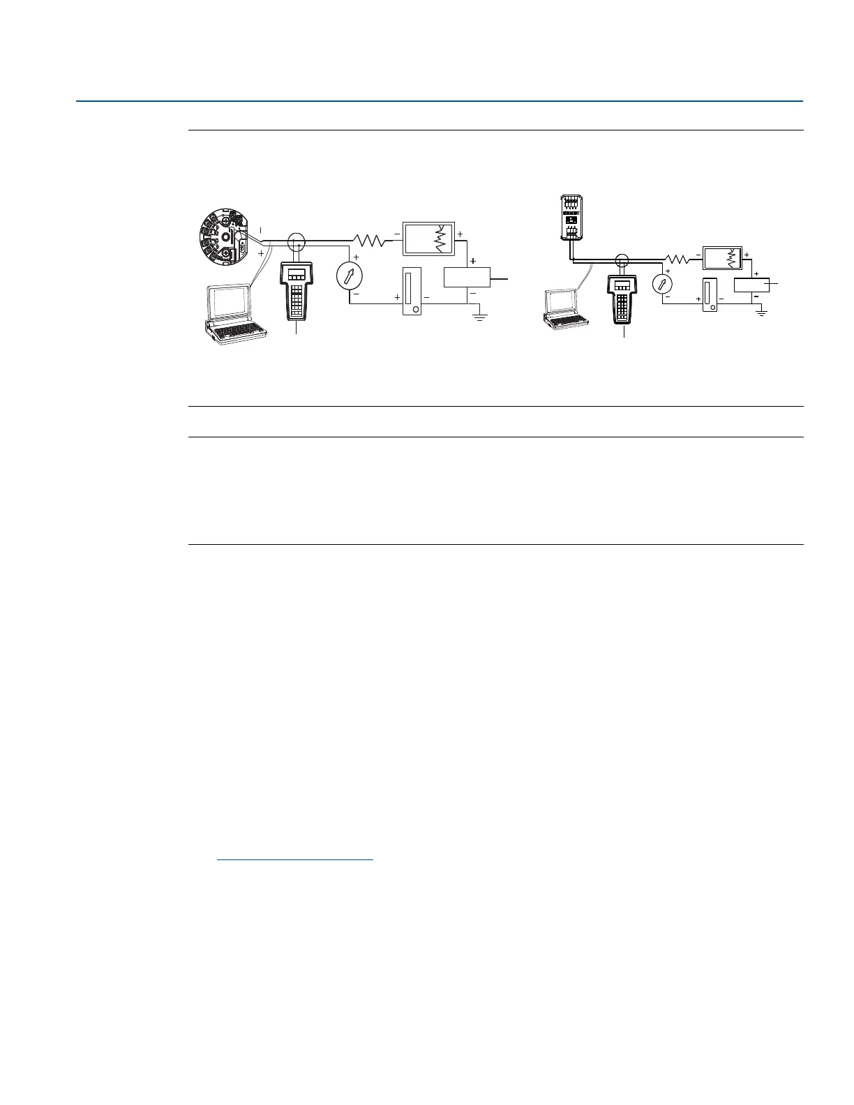
Figure 2-1. Powering the Transmitter for Bench Configuration
A. Power supply
B. Field Communicator
Note
Signal loop may be grounded at any point or left ungrounded.
A Field Communicator may be connected at any termination point in the signal loop. The signal loop
must have between 250 and 1100 Ohms load for communications.
Max torque is 6 in-lb (0.7 N-m).
2.4.2 Selecting a configuration tool
Field Communicator
The Field Communicator is a hand-held device that exchanges information with the transmitter from the
control room, the instrument site, or any wiring termination point in the loop. To facilitate
communication, connect the Field Communicator, shown in this manual, in parallel with the transmitter
(see Figure 2-1). Use the loop connection ports on the rear panel of the Field Communicator. The
connections are non-polarized. Do not make connections to the serial port or the Ni-Cad recharger jack
in explosive atmospheres. Before connecting the Field Communicator in an explosive atmosphere make
sure the instruments in the loop are installed in accordance with intrinsically safe or non-incendive field
wiring practices.
There are two interfaces available with the Field Communicator: Traditional and Dashboard interfaces.
All steps using a Field Communicator will be using Dashboard interfaces. Figure 2-2 shows the Device
Dashboard interface. As stated in “System readiness” on page 4, it is critical that the latest DD’s are
loaded into the Field Communicator for optimal transmitter performance.
Visit Emerson.com/Rosemount
to download latest DD library.
Turn on the Field Communicator by pressing the ON/OFF key. The Field Communicator will search for a
HART-compatible device and indicate when the connection is made. If the Field Communicator fails to
connect, it indicates that no device was found. If this occurs, refer to Section 6: Troubleshooting.
Rosemount 644 Head Mount and Field Mount Rosemount 644 Rail Mount
 Loading...