52
Reference Manual
00809-0200-4728, Rev SA
Installation
July 2018
Installation
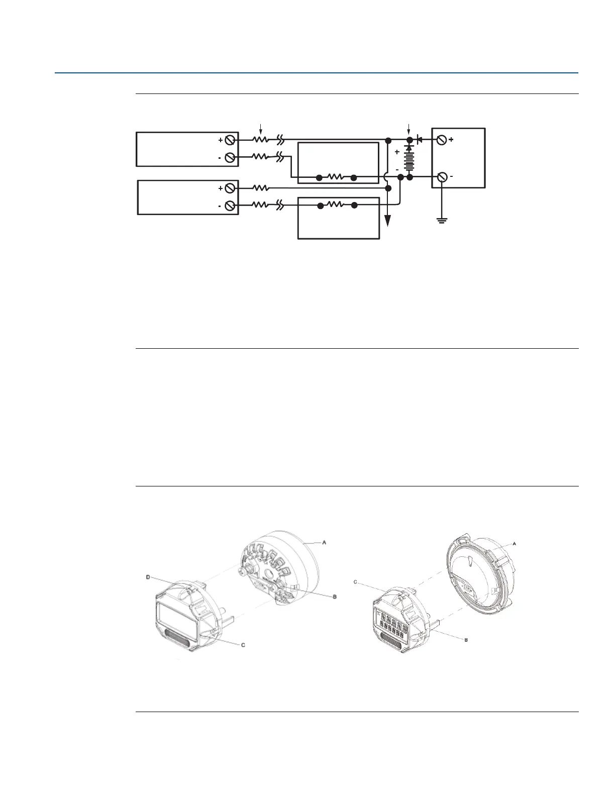
Figure 3-6. Multichannel Installations
A. Transmitter no. 1
B. Transmitter no.2
C. R
Lead
D. Readout or controller no. 1
E. Readout or controller no. 2
F. Backup battery
G. To additional transmitters
H. DC Power Supply
3.4.5 LCD display installation
The LCD display provides local indication of the transmitter output and abbreviated diagnostic messages
governing transmitter operation. Transmitters ordered with the LCD display are shipped with the meter
installed. After-market installation of the meter can be performed. After-market installation requires the
meter kit which includes:
LCD display assembly (includes LCD display, meter spacer, and two screws)
Meter cover with O-ring in place
Figure 3-7. Display Connection
Rosemount 644 Transmitter Rosemount 644 Field Mount
A. Rosemount 644 Transmitter
B. Mounting Screw and springs
C. LCD Display
D. LCD Rotation Screws
A. Rosemount 644 Field Mount
B. LCD Display
C. LCD Rotation Screws
Between 250 Ω and 1100 Ω if no load resistor.
 Loading...