August 2015
18
Quick Start Guide
Step 6: Wiring the transmitter
This section covers the wiring between the transmitter and sensor, the Modbus
output, and supplying power to the transmitter. Follow the conduit, cable, and
electrical disconnect requirements in the sections below. For sensor wiring
diagrams, see Figure 29 on page 50. For hazardous locations, refer to Appendix D
of Reference Manual 00809-0400-4444.
6.1 Conduit entries and connections
Conduit entries for the transmitter and sensor are available with
1
/2-inch NPT or
M20 connections. Conduit connections should be made in accordance with
national, local, and plant electrical codes. Unused conduit entries should be
sealed with the appropriate certified plugs. The flow sensor is rated IP68 to a
depth of 33 feet (10 meters) for 48 hours. For sensor installations requiring IP68
protection, the cable glands, conduit, and conduit plugs must be rated for IP68.
The plastic shipping plugs do not provide ingress protection.
6.2 Conduit requirements
For installations with an intrinsically safe electrode circuit, a separate conduit
for the coil cable and the electrode cable may be required. Refer to
Appendix D of Reference Manual 00809-0400-4444.
For installations with non-intrinsically safe electrode circuit, or when using the
combination cable, a single dedicated conduit run for the coil drive and
electrode cable between the sensor and the remote transmitter may be
acceptable. Bundled cables from other equipment in a single conduit are likely
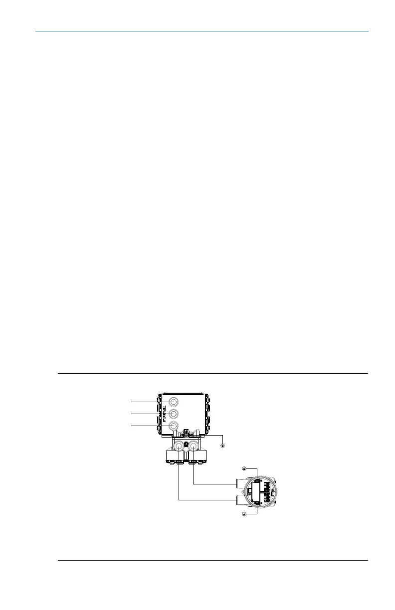
to create interference and noise in the system. See Figure 15.
Electrode cables should not be run together and should not be in the same
cable tray with power cables.
Output cables should not be run together with power cables.
Select conduit size appropriate to feed cables through to the flowmeter.
Figure 15. Best Practice Conduit Preparation
A. Power
B. Output
C. Coil
D. Electrode

 Loading...


