Quick Installation Guide
00825-0100-4727, Rev CC
January 2013
Rosemount 8700 Series
7
If leakage has not stopped at the suggested torque values, the bolts can be tightened in
additional 10 percent increments until the joint stops leaking, or until the measured torque
value reaches the maximum torque value of the bolts. Practical consideration for the
integrity of the liner often leads the user to distinct torque values to stop leakage due to the
unique combinations of flanges, bolts, gaskets, and sensor liner material.
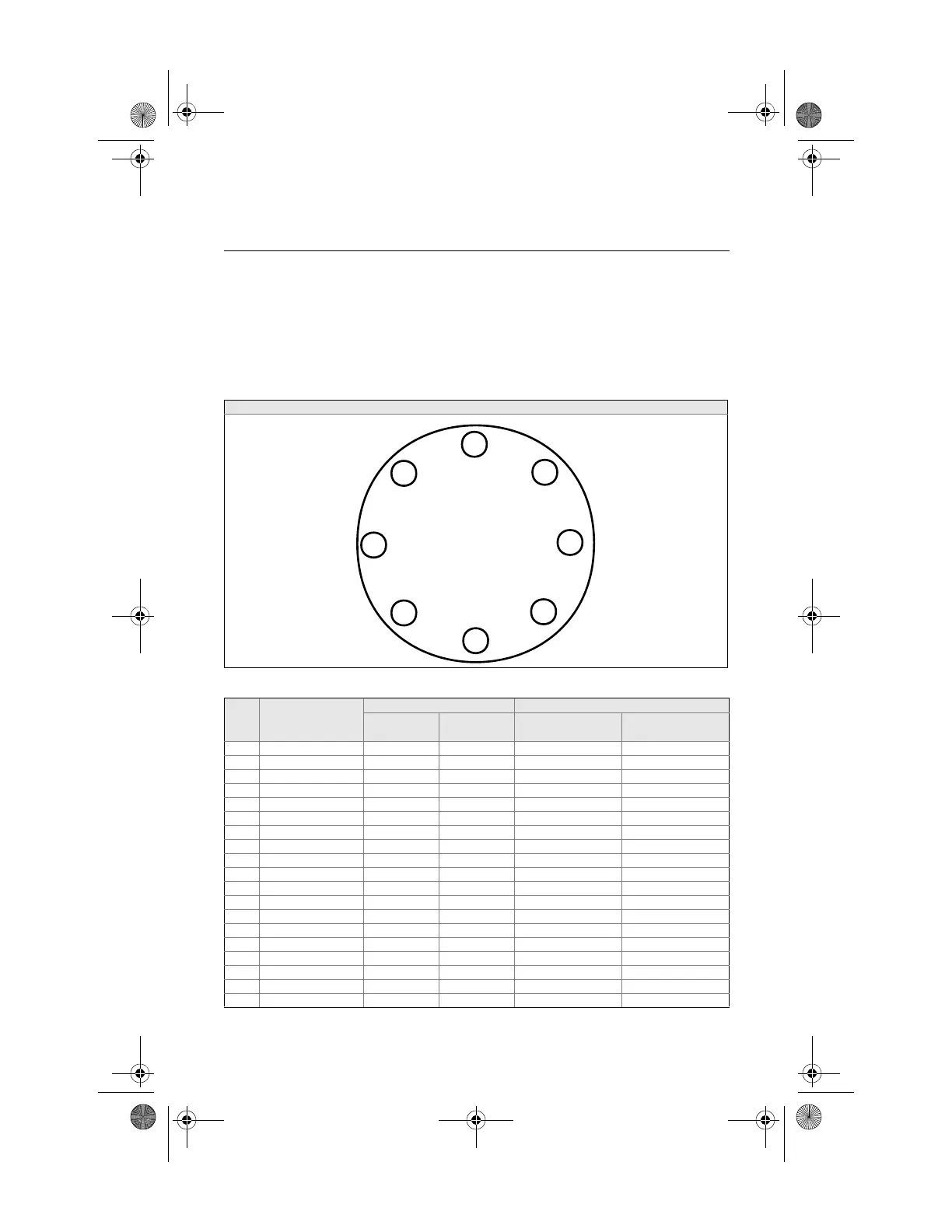
Check for leaks at the flanges after tightening the bolts. Failure to use the correct tightening
methods can result in severe damage. Sensors require a second tightening 24 hours after
the initial installation. Over time, sensor liner materials may deform under pressure.
Figure 6. Flange Bolt Torquing Sequence
Table 1. Suggested Flange Bolt Torque Values for Rosemount 8705 and 8707 High-Signal Sensors
Size
Code
Line Size
PTFE/ETFE/PFA liners Polyurethane/Neoprene/Adiprene liner
Class 150
(pound-feet)
Class 300
(pound-feet)
Class 150
(pound-feet)
Class 300
(pound-feet)
005 0.5 in. (15 mm) 8 8 - -
010 1 in. (25 mm) 8 12 - -
015 1.5 in. (40 mm) 13 25 7 18
020 2 in. (50 mm) 19 17 14 11
025 2.5 in. (65mm) 22 24 17 16
030 3 in. (80 mm) 34 35 23 23
040 4 in. (100 mm) 26 50 17 32
050 5 in. (125mm) 36 60 25 35
060 6 in. (150mm) 45 50 30 37
080 8 in. (200 mm) 60 82 42 55
100 10 in. (250 mm) 55 80 40 70
120 12 in. (300 mm) 65 125 55 105
140 14 in. (350 mm) 85 110 70 95
160 16 in. (400 mm) 85 160 65 140
180 18 in. (450 mm) 120 170 95 150
200 20 in. (500 mm) 110 175 90 150
240 24 in. (600 mm) 165 280 140 250
300 30 in. (750 mm) 195 415 165 375
360 36 in. (900 mm) 280 575 245 525
4727_revCC_QIG.fm Page 7 Thursday, January 10, 2013 6:08 PM
Artisan Technology Group - Quality Instrumentation ... Guaranteed | (888) 88-SOURCE | www.artisantg.com