Do you have a question about the Emerson Rosemount 8705 and is the answer not in the manual?
Proper sensor placement requires specific upstream and downstream pipe diameter lengths for accuracy.
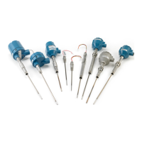
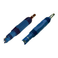
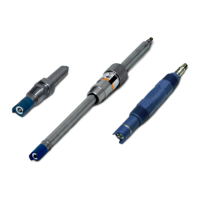
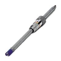
Install sensor ensuring it remains full, with correct electrode orientation for optimal performance.
Covers gasket placement, flange bolt tightening sequence, and torque values for flanged sensors.
Details gasket placement, alignment spacers, stud specs, and torque for wafer sensors.
Describes gasket requirements and alignment/bolting for sanitary fittings.
Guidelines for conduit ports, connections, requirements, and cable preparation for signal integrity.
Details wiring connections between sensor and transmitter, including cable types and terminal assignments.
Covers transmitter power requirements, supply wire specs, disconnects, installation category, and overcurrent protection.
Approved locations, EMC, safety requirements, CE marking, and general guidelines.
Specific PED compliance for flowmeter models and line sizes.
Details Factory Mutual (FM) and Canadian Standards Association (CSA) certifications.
Covers ATEX, IECEx, and other international certifications with installation and safety conditions.
| Model | 8705 |
|---|---|
| Manufacturer | Emerson |
| Application | Flow Measurement |
| Material | Stainless Steel |
| Process Connection | Flanged |
| Type | Magnetic Flow Meter, Flanged |
| Lining Material Options | PTFE, ETFE, PFA, Polyurethane, Neoprene |
| Electrode Material Options | Stainless Steel, Hastelloy C, Titanium, Tantalum |
| Size Range | 1/2 to 36 in. (15 to 900 mm) |
| Pressure Rating | ASME B16.5 |
| Process Temperature | -29 to 177°C |
| Output | 4-20 mA, HART, Foundation Fieldbus |
| Power Supply | 12-42 VDC |
| Communication Protocol | HART, FOUNDATION Fieldbus |
| Certification | ATEX, IECEx, CSA |