3 Operation
3.1 Power up the detector
Procedure
After connecting the detector to power, wait up to 60 seconds for the detector to
completed the initial start-up procedure.
Note
Turning on the detector initiates the following sequence of events:
a. The yellow light-emitting diode (LED) flashes at 4 Hz.
b. The built-in test (BIT) is executed.
c. BIT completes.
d. Detector enters Normal mode, indicated by:
• Flashing green LED at 1 Hz.
• Fault relay contacts closing.
• mA output is 4 mA (for models featuring analog [voltage] output, this will be 2 V).
3.2 Test flame detectors
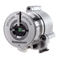
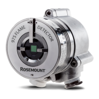
You can use the Rosemount flame simulators to test the Rosemount 975 flame detectors.
You can also use the manual built-in text (BIT) to test the flame detectors.
Table 3-1: Flame simulator compatibility
Rosemount flame simulator model Rosemount 975 flame detector model
FS-HR-975 Rosemount 975HR
FS-IR-975 Rosemount 975MR
FS-UVIR-975 Rosemount 975UF and 975UR
To test a flame detector:
Procedure
1. Power up the system and wait for up to 60 seconds for the detector to return to
normal status.
The Power light-emitting diode (LED) turns on.
2. Ensure all indicators show Normal.
Postrequisites
For full instructions on testing with a flame simulator, see the relevant Reference Manual.
Table 3-2: Flame simulator Reference Manuals
Rosemount flame simulator Reference Manual
FS-HR-975 00809-0900-4975
FS-IR-975 00809-0500-4975
Manual Operation
00809-1400-4975 September2023
Rosemount 975 25