Contents
Chapter 1 Introduction...............................................................................................................................7
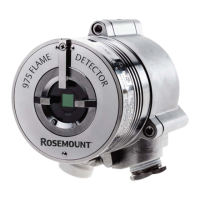
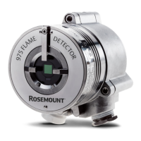
1.1 Product overview.........................................................................................................................7
1.2 Models.......................................................................................................................................... 7
Chapter 2 Installation.................................................................................................................................9
2.1 Installation guidelines.................................................................................................................9
2.2 Preparation for use..................................................................................................................... 9
2.3 Attach detector to tilt mount................................................................................................... 14
2.4 Open the back cover................................................................................................................. 15
2.5 Wire terminals and ground cable............................................................................................17
2.6 Install the protective cover.......................................................................................................22
2.7 Aim the detector........................................................................................................................22
2.8 Changing default detector settings ....................................................................................... 23
Chapter 3 Operation................................................................................................................................. 25
3.1 Power up the detector.............................................................................................................. 25
3.2 Test flame detectors................................................................................................................. 25
Chapter 4 Initial setup..............................................................................................................................27
4.1 Continuous feature test............................................................................................................27
4.2 Response to fault indication.................................................................................................... 27
4.3 Built-in test (BIT)........................................................................................................................ 27
Chapter 5 Maintenance............................................................................................................................29
5.1 Keeping maintenance records.................................................................................................29
5.2 Clean the detector.....................................................................................................................29
Chapter 6 Troubleshooting...................................................................................................................... 31
6.1 Light-emitting diode (LED) is off, fault relay is open, 0-20 mA shows 0 mA, analog
voltage output is 0 V...................................................................................................................31
6.2 Light-emitting diode (LED) flashes yellow at 4 Hz, fault relay is open, 0-20 mA
shows 1 mA................................................................................................................................. 31
6.3 Light-emitting diode (LED) flashes yellow at 4 Hz, relay is open, 0-20 mA shows 2 mA.. 31
6.4 Light-emitting diode (LED) constantly red, alarm relay energized, 0-20 mA
indicates alarm............................................................................................................................32
6.5 No HART
®
communication, 0-20 mA shows 0 mA.................................................................32
Chapter 7 Specifications...........................................................................................................................33
7.1 Technical specifications............................................................................................................ 33
7.2 Electrical specifications.............................................................................................................35
7.3 Mechanical specifications.........................................................................................................36
Appendix A Reference data........................................................................................................................ 39
A.1 Ordering information, specifications, dimensional drawings, and installation
drawings...................................................................................................................................... 39
A.2 Product certifications................................................................................................................39
Manual Contents
00809-1400-4975 September2023
Rosemount 975 5