Unidrive M / HS Frame 7 to 10 Power Installation Guide 11
Issue Number: 5
Safety information
Product information
Mechanical installation Electrical installation Technical data UL listing information
2 Product information
2.1 Introduction
This guide provides the information necessary to install the following drive models:
Unidrive M200 to M400 frame 7 to 9
Unidrive M600 to M702 frame 7 to 10
Unidrive HS70 to HS72 frame 7 to 10
This guide focuses on the drive power section, for example: electrical installation of the supply /
motor cables and mechanical installation of the drive.
For information about the drive control section, for example: parameter set up information, control
and encoder connections, please refer to the Control User Guide.
2.2 Model number
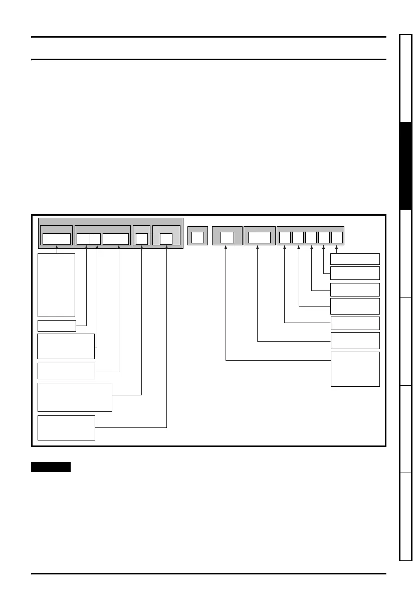
The model numbers for the Unidrive M/HS product range are formed as illustrated below:
Figure 2-1 Model number
* Only shown on frame 9E and 10 identification label
For simplicity a Frame 9 drive with no internal choke (i.e. Model 09xxxxxxE) is referred to as a Frame
9E and a Frame 9 drive with an internal choke (i.e. Model 09xxxxxxA) is referred to as a Frame 9A.
Any reference to Frame 9 is applicable to both sizes 9E and 9A. All Frame size 10 drives are
supplied with no internal choke.
Identification Label
Electrical Specifications
Derivative
Frame Size:
Voltage Rating:
Current Rating:
Heavy Duty current rating x 10
Power Format:
Reserved
0
Optional Build
Customer Code
01
A B 1 00
Customer Code:
00 = 50 Hz
01 = 60 Hz
Reserved:
Conformal Coating:
0 = Standard
IP / NEMA Rating:
1 = IP20 / NEMA 1
Brake Transistor:
B
N = No
= Brake
Cooling:
A = Air
Documentation
1
2 - 200 V (200 - 240 ± 10 %)
4 10 %)- 400 V (380 - 480 ±
5 10 %)- 575 V (500 - 575 ±
6 10 %)- 690 V (500 - 690 ±
Power
Format
M600 - 03 4 00078 A
Configuration*
1
A - AC in AC out (with internal choke)
D - DC in AC out (Inverter)
C - AC in DC out (Rectifier)
E - AC in AC out (without internal choke)
T - AC in AC out (12P rectifier plus inverter)
Configuration:
1 - Standard
U - No Control
M - Master
F - Follower
Documentation:
0 - Supplied separately
1 - English
2 - French
3 - Italian
4 - German
5 - Spanish
Unidrive M200
Unidrive M201
Unidrive M300
Unidrive M400
Unidrive M600
Unidrive M700
Unidrive M701
Unidrive M702
Product Line
Unidrive HS70
Unidrive HS71
Unidrive HS72
Unidrive M frame7 to 10 Power Installation Guide issue5.book Page 11 Tuesday, May 24, 2016 11:52 AM

 Loading...


