44 Unidrive M / HS Frame 7 to 10 Power Installation Guide
Issue Number: 5
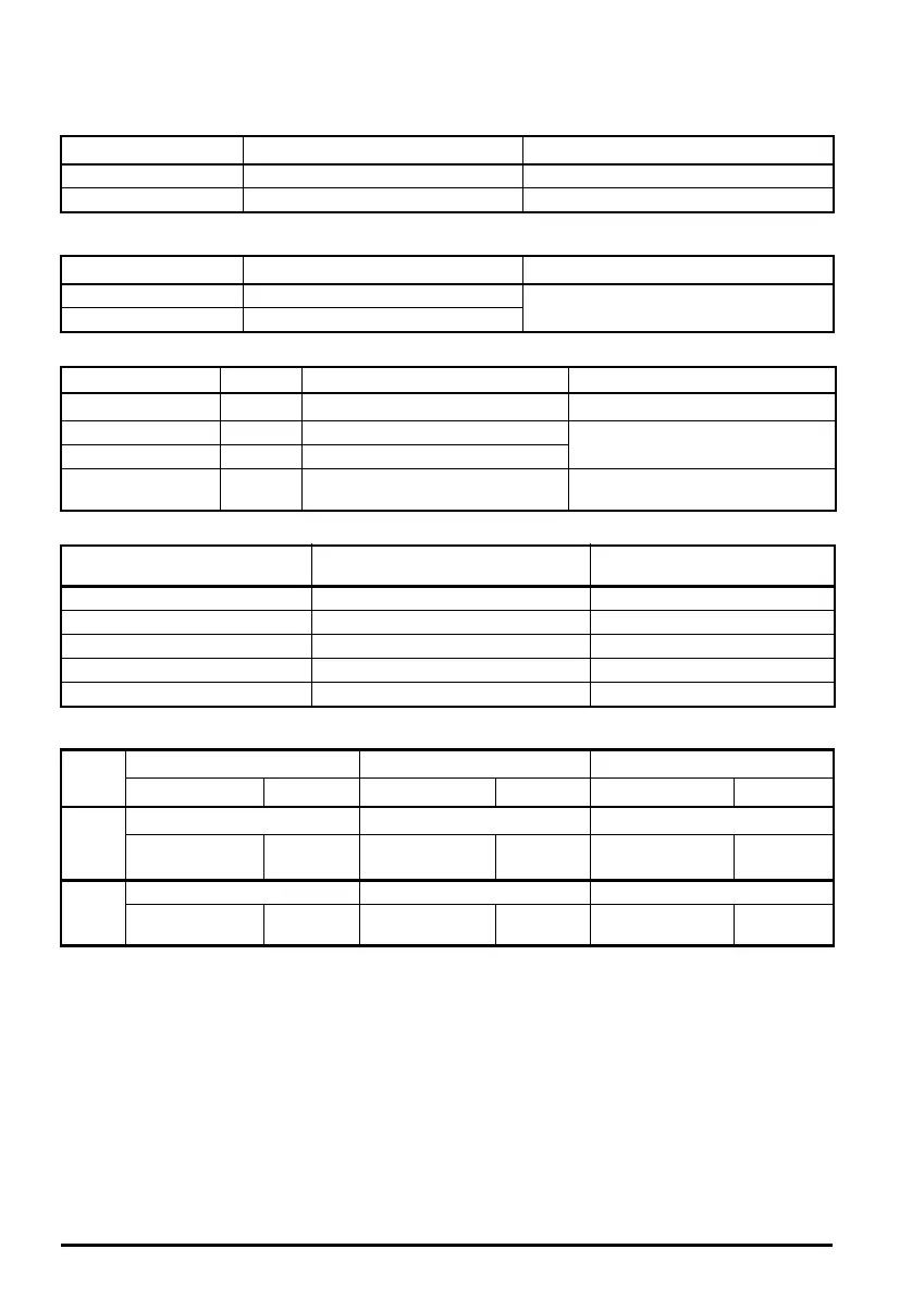
3.10 Terminal size and torque settings
Table 3-13 Drive control terminal data
Table 3-14 Drive relay terminal data
Table 3-15 Terminal block maximimum cable sizes
Table 3-16 Maximum crimp/lug sizes for frame size 8 to 10
Table 3-17 Drive power terminal data
Model Connection type Torque setting
M200 to M400 Screw terminals 0.2 N m (0.15 lb ft)
M600 to M702 Plug-in terminal block 0.5 N m (0.4 lb ft)
Model Connection type Torque setting
M200 to M400 Screw terminals
0.5 N m (0.4 lb ft)
M600 to M702 Plug-in terminal block
Model
Size Terminal block description Maximum cable size
All All Control connector
1.5 mm
2
(16 AWG)
All All 2 way relay connector
2.5 mm
2
(14 AWG)
M300 to M400 7 to 9 STO connector
M600 to M702 All
2 way low voltage power 24V supply
connector
1.5 mm
2
(16 AWG)
Terminals
Maximum standard crimp (mm
2
)
Maximum standard US lug
(kcmil)
AC supply connections 2 x 185 2 x 500
AC supply ground 2 x 120 1 x 350
Motor connections 2 x 150 2 x 350
Drive output ground 2 x 150 1 x 350
Brake connection 2 x 150 2 x 350
Model
size
AC and motor terminals DC and braking Ground terminal
Recommended Maximum Recommended Maximum Recommended Maximum
7
M8 Nut (13 mm AF) M8 Nut (13 mm AF) M8 Nut (13 mm AF)
12 N m
(8.85 lb ft)
14 N m
(10 lb ft)
12 N m
(8.85 lb ft)
14 N m
(10 lb ft)
12 N m
(8.85 lb ft)
14 N m
(10 lb ft)
8 to 10
M10 Nut (17 mm AF) M10 Nut (17 mm AF) M10 Nut (17 mm AF)
15 N m
(11.1 Ib ft)
20 N m
(14.8 Ib ft)
15 N m
(11.1 Ib ft)
20 N m
(14.8 Ib ft)
15 N m
(11.1 Ib ft)
20 N m
(14.8 Ib ft)
Unidrive M frame7 to 10 Power Installation Guide issue5.book Page 44 Tuesday, May 24, 2016 11:52 AM

 Loading...


