22 Unidrive M / HS Frame 7 to 10 Power Installation Guide
Issue Number: 5
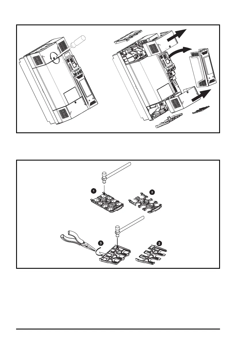
Figure 3-4 Removing the size 7 to 10 terminal covers (Unidrive M600 to M702 size 7 shown)
When replacing the terminal covers, the screws should be tightened to a maximum torque of 1 N m
(0.7 lb ft).
3.3.2 Removing the finger-guard and DC terminal cover break-outs
Figure 3-5 Removing the finger-guard break-outs
All sizes:
Place the finger-guard on a flat solid surface and hit relevant break-outs with hammer as shown (1).
Pliers can be used to remove the breakouts, grasp the relevant break-out with pliers and twist it as
shown (3). Continue until all the required break-outs have been removed (2). Remove any flash /
sharp edges once the break-outs have been removed.
Unidrive M frame7 to 10 Power Installation Guide issue5.book Page 22 Tuesday, May 24, 2016 11:52 AM

 Loading...


