Unidrive M / HS Frame 7 to 10 Power Installation Guide 25
Issue Number: 5
Safety information Product information
Mechanical installation
Electrical installation Technical data UL listing information
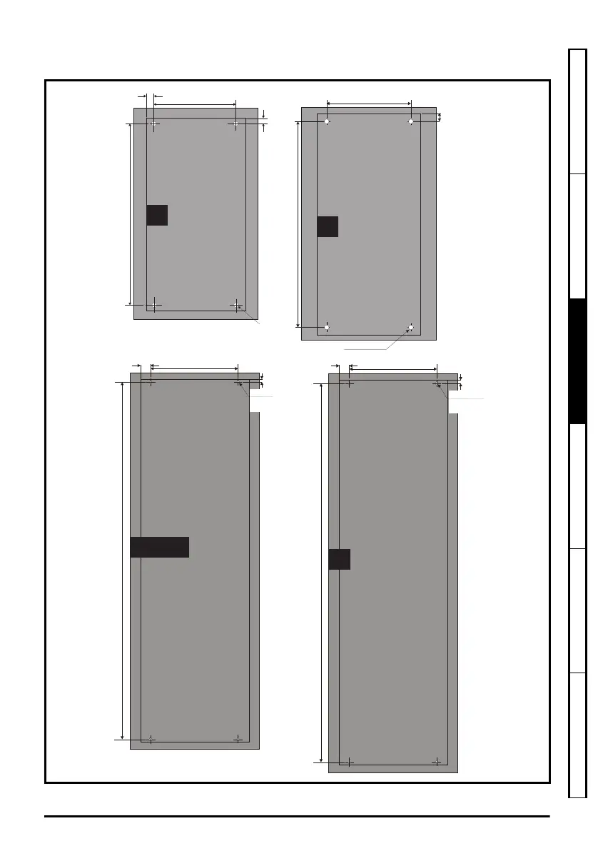
3.4.2 Surface mounting
Figure 3-7 Surface mounting dimensions (size 7 to 10)
220 mm (8.66 in)
Æ
9mm (0.35 in)
538 mm (21.18)
25 mm
(0.98 in)
10 mm
(0.39 in)
784 mm (30.87 in)
8
259 mm (10.20 in)
(0.35 in)
x 4 holes
9 mm
(0.35 in)
26 mm
(1.02 in)
Æ
9.0 mm
9.5 mm
(0.37 in)
259 mm (10.20 in)
(0.35 in)
x 4 holes
9 mm
(0.35 in)
26 mm
(1.02 in)
Æ
9.0 mm
1090 mm (42.91 in)
9.0 mm (0.35 in)
x 4 holes
Æ
259 mm (10.20 in)
1051 mm (41.38 in)
7
8
9E / 10E
9A
Unidrive M frame7 to 10 Power Installation Guide issue5.book Page 25 Tuesday, May 24, 2016 11:52 AM

 Loading...


