Unidrive M / HS Frame 7 to 10 Power Installation Guide 27
Issue Number: 5
Safety information Product information
Mechanical installation
Electrical installation Technical data UL listing information
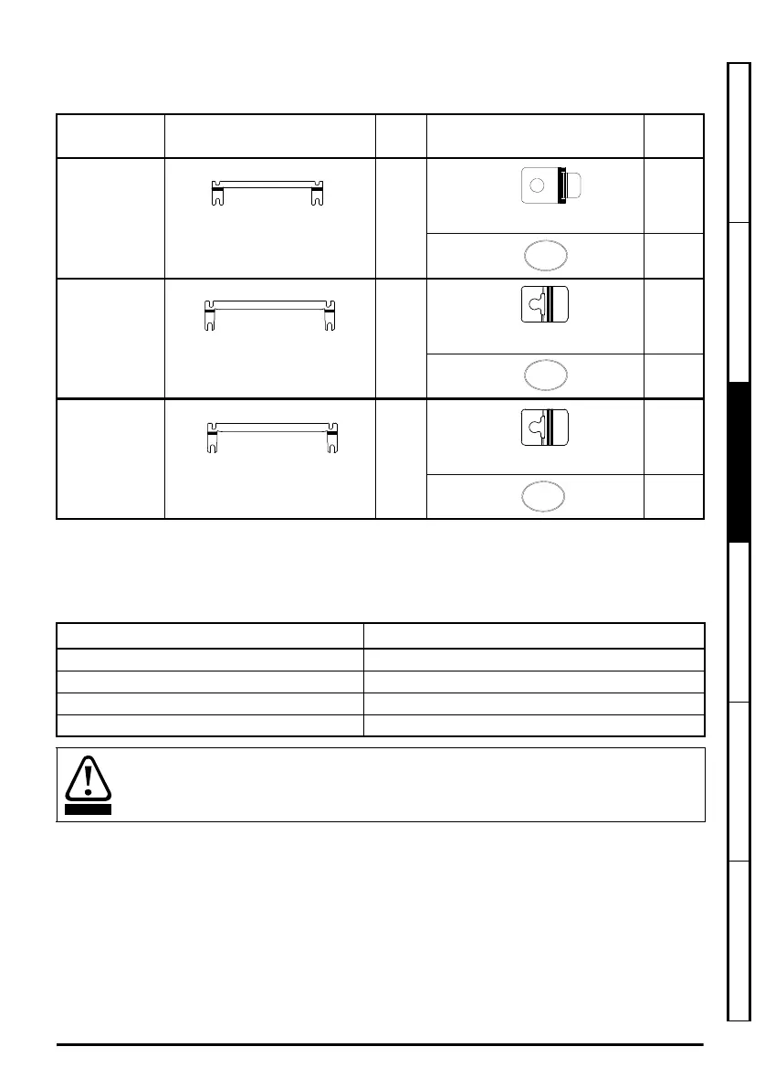
3.4.4 Mounting brackets
Table 3-2 Mounting brackets
* Surface mounting bracket are also used when through-panel mounting.
The through panel mounting kit is not supplied with the drive and can be purchased separately, below
are the relevant part numbers:
Frame size
Surface mounting kit
(supplied with drive)
Qty
Optional through-panel
mounting kit
Qty
7
Hole size: 9 mm (0.35 in)
x 2*
x 2
Hole size: 9 mm (0.35 in)
x 1
8
Hole size: 9 mm (0.35 in)
x 2*
x 6
Hole size: 5.5 mm (0.22 in)
x 1
9A / 9E and
10E
Hole size: 9 mm (0.35 in)
x 2*
x 8
Hole size: 5.5 mm (0.22 in)
x 1
Size CT part number
7 3470-0079
8 3470-0083
9A 3470-0119
9E/10E 3470-0105
If the drive has been used at high load levels for a period of time, the heatsink can reach
temperatures in excess of 70 °C (158 °F). Human contact with the heatsink should be
prevented.
Unidrive M frame7 to 10 Power Installation Guide issue5.book Page 27 Tuesday, May 24, 2016 11:52 AM

 Loading...


