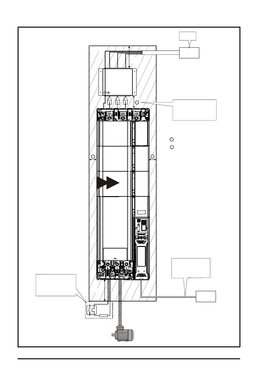
Ensure minimum clearances
are maintained for the drive
and external EMC filter. Forced
or convection air-flow must not
be restricted by any object or
cabling
Note
For EMC compliance:
1) When using an external EMC
filter, one filter is required for
each drive
2) Power cabling must be at
least 100mm (4in) from the
drive in all directions
A
B
= 60 mm (2.37 in)
= 45 mm (1.77 in)
B B
A
AC supply
contactor and
fuses or MCB
Locate as
required
Locate as
required
Enclosure
³100mm
(4in)
³100mm
(4in)
Signal cables
Plan for all signal cables
to be routed at least
300 mm (12 in) from the
drive and any power cable
controller
External
Optional braking
resistor and overload
Locate optional braking
resistor external to
cubicle (preferably near
to or on top of the cubicle).
Locate the overload
protection device as required
9 10

 Loading...


