Unidrive M / HS Frame 7 to 10 Power Installation Guide 49
Issue Number: 5
Safety information Product information
Mechanical installation
Electrical installation Technical data UL listing information
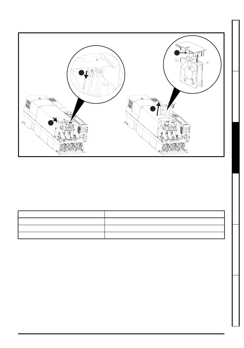
3.11.4 Size 7 to 10 auxiliary (capacitor bank) fan replacement
Figure 3-24 Size 7 to 10 auxiliary (capacitor bank) fan replacement
Auxiliary fan removal procedure
1) Disconnect fan wiring connector shown
2) Slide fan housing in the direction shown using tongue shown in enlarged diagram of fan
3) Withdraw fan housing from the drive
After fan has been replaced, reverse the above steps to refit.
Table 3-21 Auxiliary (capacitor bank) fan part numbers
Drive model Auxiliary (capacitor bank) fan part number
Size 7 3251-0041
Size 8 3251-2249
Size 9 to 10 3251-0042
Unidrive M frame7 to 10 Power Installation Guide issue5.book Page 49 Tuesday, May 24, 2016 11:52 AM

 Loading...


