Unidrive M / HS Frame 7 to 10 Power Installation Guide 75
Issue Number: 5
Safety information Product information Mechanical installation
Electrical installation
Technical data UL listing information
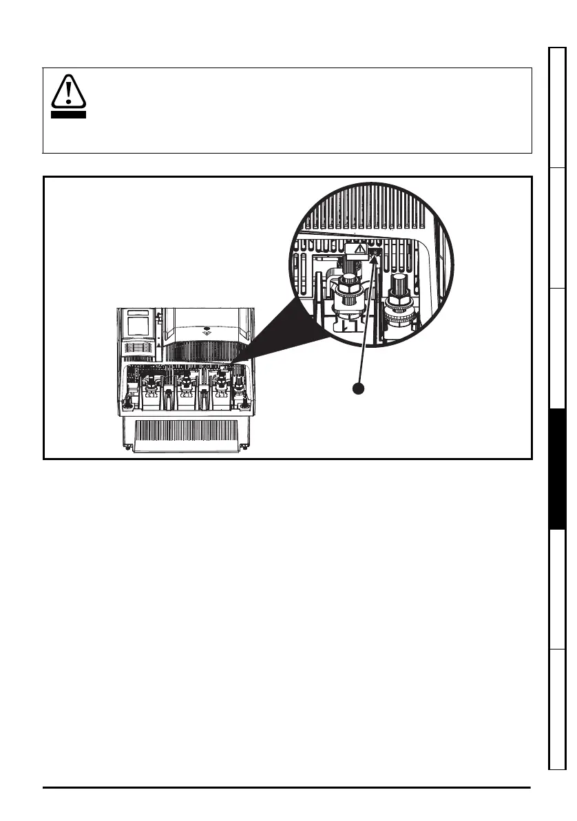
4.11.3 Line to ground varistors
Figure 4-14 Removal of size 9E and 10E line to ground varistors
To electrically disconnect the line to ground varistors, remove the screw as highlighted above (1).
The line to ground varistors should only be removed in special circumstances such as
ungrounded supplies with more than one source, for example on ships. Where the line to
ground varistors are removed, ensure that line to ground transients are limited to values
of category II. This is to ensure that line to ground transients do not exceed 4 kV as the
drive insulation system from power to ground is designed to category II.Contact the
supplier of the drive for more information.
Unidrive M frame7 to 10 Power Installation Guide issue5.book Page 75 Tuesday, May 24, 2016 11:52 AM

 Loading...


