84 Unidrive M / HS Frame 7 to 10 Power Installation Guide
Issue Number: 5
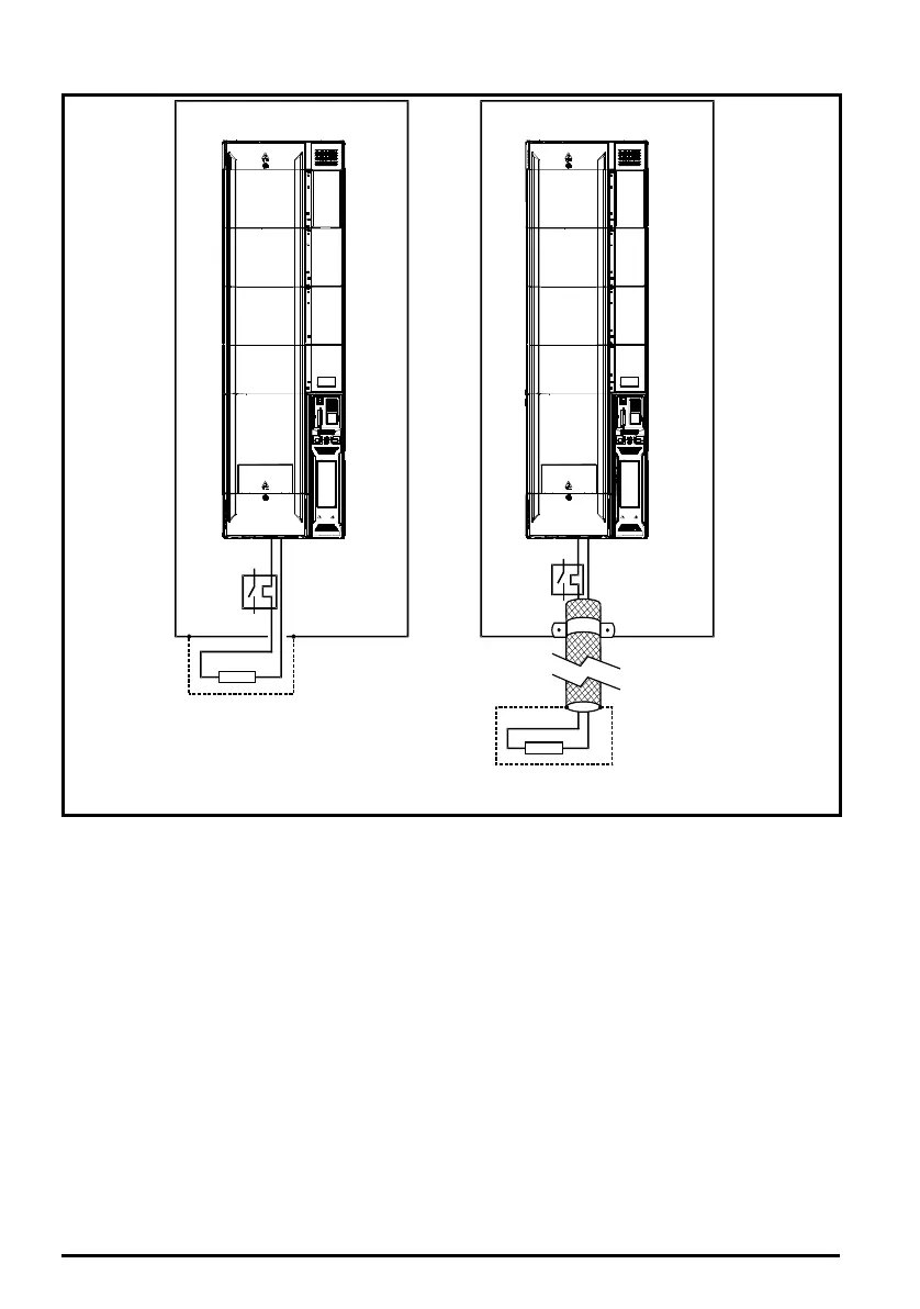
Figure 4-23 Shielding requirements of optional external braking resistor
If the control wiring is to leave the enclosure, it must be shielded and the shield(s) clamped to the
drive using the grounding bracket as shown in Figure 4-24. Remove the outer insulating cover of the
cable to ensure the shield(s) make contact with the bracket, but keep the shield(s) intact until as
close as possible to the terminals
Alternatively, wiring may be passed through a ferrite ring, part no. 3225-1004.
+DC BR
Optional external
braking resistor
Enclosure
+DC BR
Optional external
braking resistor
Enclosure
OR
Unidrive M frame7 to 10 Power Installation Guide issue5.book Page 84 Tuesday, May 24, 2016 11:52 AM

 Loading...


