2 – 4
Section 2 • Operational Descriptions
Blower Package PLC Operation Manual •Vilter/Emerson • 35391BLP
blower. If a blower shuts down due to a blower-specifi c
trip, other blowers that do not have active trips will be
allowed to run.
The “Alarm Reset” pushbutton on the overview screen
will reset any active alarms or trips if the abnormal condi-
tion has been removed.
For a comprehensive list of alarms and trips and possible
causes, see the troubleshooting guide in this manual.
The “Alarm Reset” pushbutton on the overview screen
will reset any active alarms or trips if the abnormal
condition has been removed.
For a comprehensive list of alarms and trips and possible
causes, see the troubleshooting guide in this manual.
INHIBIT
LOAD
FORCE
UNLOAD TO
FORCE
UNLOAD AT
DISCHARGE
PRESSURE
LOW SUCTION PRESSURE
A
B
C
D
INHIBIT
LOAD
FORCE
UNLOAD TO
FORCE
UNLOAD AT
HIGH DISCHARGE PRESSURE
A
B
C
D
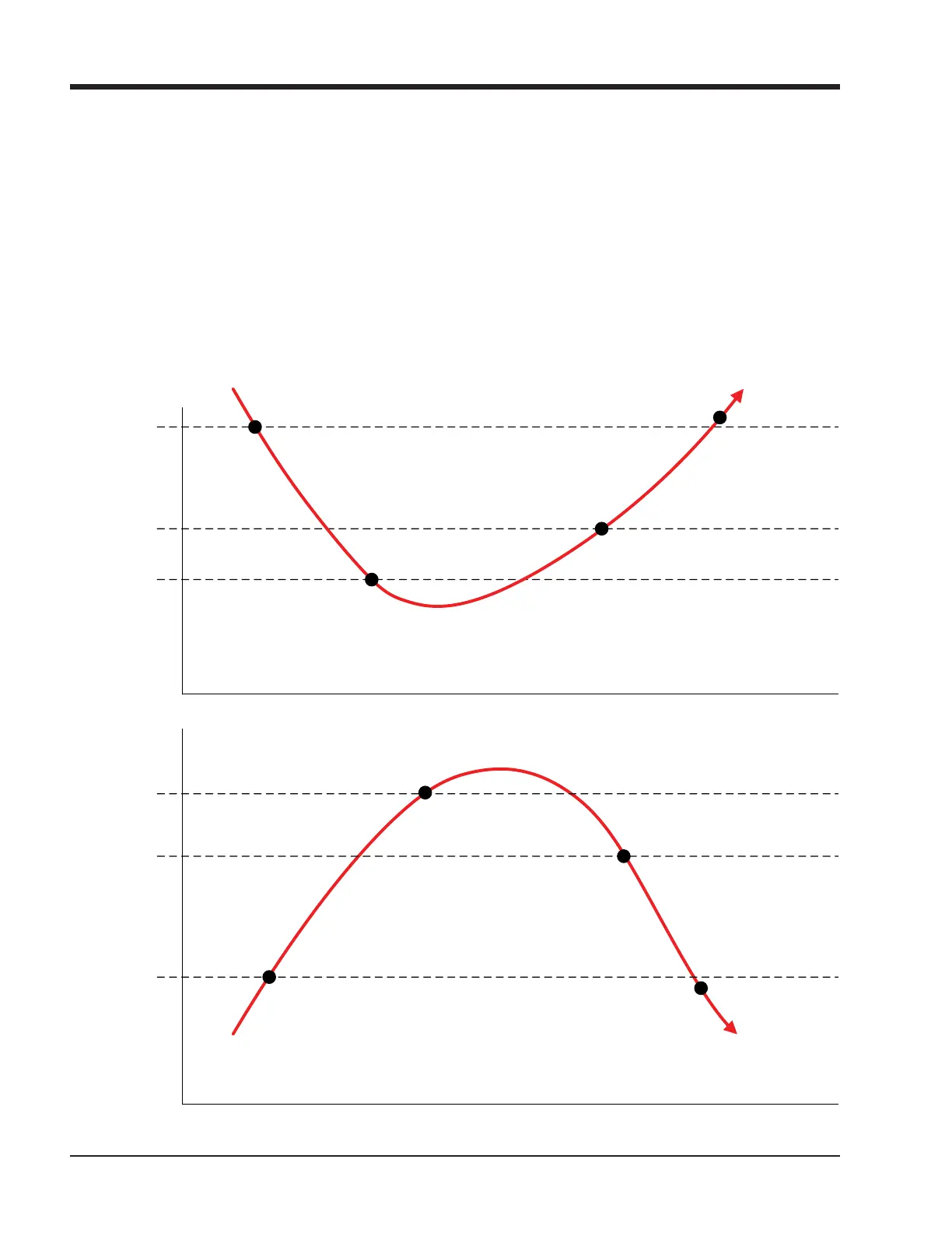
(A) CAPACITY SLIDE WILL NOT INCREASE
(B & C) CAPACITY SLIDE WILL DECREASE UNTIL PRESSURE REACHES “C”
(D) BLOWER SPEED MAY INCREASE
(A) CAPACITY SLIDE WILL NOT INCREASE
(B & C) FORCED UNLOAD UNTIL DISCHARGE PRESSURE/AMPS REACHES “C”
(D) BLOWER SPEED ALLOWED TO INCREASE
SUCTION
PRESSURE
Figure 2-1. Operational Diagram - Load Limits / Forced Unloading (Example)



 To Next Page