8 – 1
Section 8 • Alarm and Trip Setpoints
Blower Package PLC Operation Manual •Vilter/Emerson • 35391BLP
Alarm and Trip Setpoints
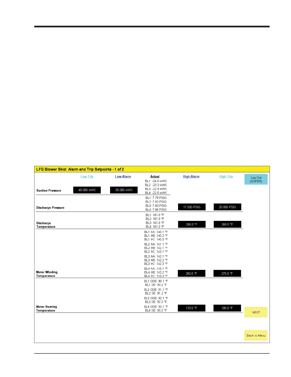
Figure 8-1. Alarm and Trip Setpoints Screen - 1 of 2
NOTE
Screens may have inverted colors for ease of
readability.
The blower controller continuously monitors opera-
tional and process data and annunciates an alarm and/
or shuts the blower down if any condition becomes ab-
normal. The alarm and trip points for some of the op-
erational and process data are adjustable by the user in
the alarm and trip setpoints screens. The alarm and trip
setpoints are interlocked such that a low alarm may not
be set lower than a low trip, and a high trip may not be
set below a high alarm.
Actual values of the specifi c operational and process
data is shown in the column in the middle of the screen.
Setpoints are only shown for applicable alarm and trip
points.
Alarm and Trip Setpoints - Page 1
• Suction Pressure: Low Alarm and Low Trip setpoints
for suction pressure at the individual blower or head-
er (if selected).
• Discharge Pressure: High Alarm and High Trip set-
points for discharge pressure at the individual blower
or header (if selected).
• Discharge Temperature: High Alarm and High Trip
setpoints for blower discharge temperature.
• Motor Winding Temperature: High Alarm and High
Trip setpoints for temperature of the main motor
windings, if motor winding RTDs are installed.
• Motor Bearing Temperature: High Alarm and High
Trip setpoints for temperature of the main motor
bearings, if motor bearing RTDs are installed.



 To Next Page