7 – 5
Section 7 • Blower Configuration and Control Setpoints
Blower Package PLC Operation Manual •Vilter/Emerson • 35391BLP
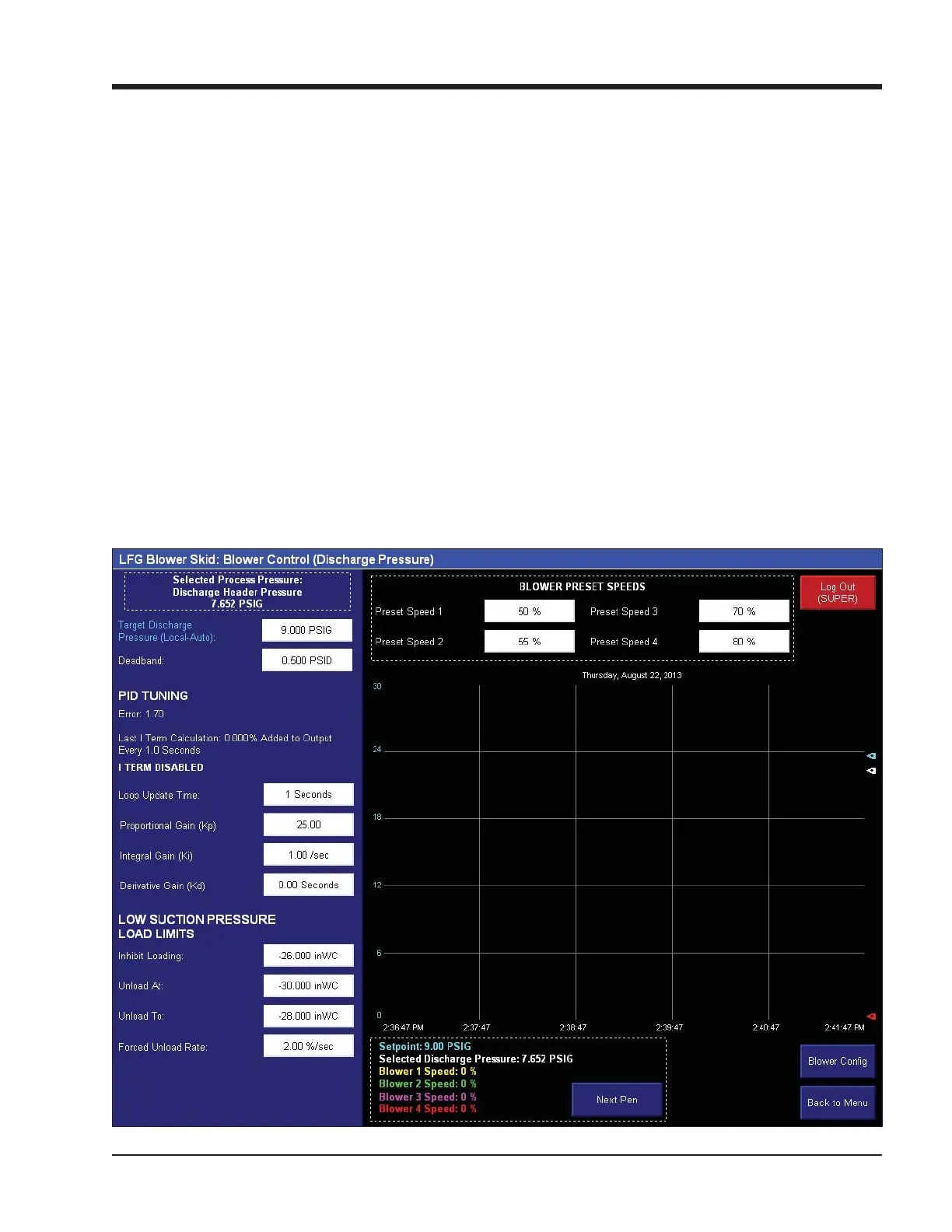
Figure 7-4. Blower Control Screen - Discharge Pressure
Blower Control Setpoints - Discharge Pressure
The Blower Control Setpoints page 1 (Discharge
Pressure) screen appears when navigating to “Blower
Control Setpoints” from the menu screen when
Discharge Pressure control is selected. Setpoints for
desired discharge pressure, PID Tuning, and Load Limits
are accessible from this screen. For more information
and operational descriptions, see section 2 “Operational
Descriptions.”
DISCHARGE PRESSURE CONTROL
• Target Discharge Pressure: This is the desired suction
pressure the blower will try to maintain.
• Deadband: This is a range of pressures above and be-
low the Target Suction Pressure. Within this range,
no speed adjustments will be made.
PID TUNING
• Loop Update Time: This is the cycle time of the PID
controller.
• Proportional Gain (Kp): This is the proportional con-
stant of the PID calculation.
• Integral Gain (Ki): This is the integral constant of the
PID calculation.
• Derivative Gain (Kd): This is the derivative constant of
the PID calculation.
LOW SUCTION PRESSURE LOAD LIMITS
• Inhibit Loading: Blower will not be allowed to increase
speed if Suction Pressure falls below this setpoint.
• Unload At: Blower will begin continuously decreasing
speed if Suction Pressure falls below this setpoint.
• Unload To: If forced unloading is active, the blower
will decrease its speed continuously until Suction
Pressure reaches this setpoint.



 To Next Page