10 – 1
Section 10 • Diagnostic Screens
Blower Package PLC Operation Manual •Vilter/Emerson • 35391BLP
IO/Comms Diagnostics Screen
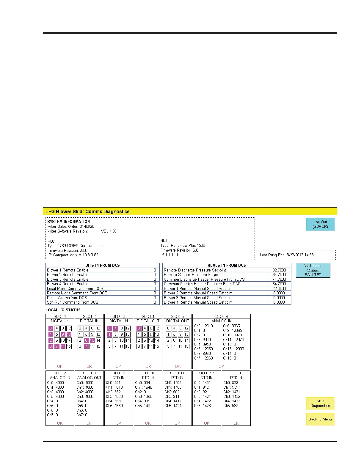
Figure 10-1. IO/Comms Diagnostics Screen
COMMS DIAGNOSTICS AND I/O STATUS
NOTE
Some screens may have inverted colors for ease of
readability.
The IO/Comms Diagnostics Screen is divided into 3
sections.
• SYSTEM INFORMATION
• Shows basic information about the Blower PLC
panel: Vilter sales order number, Software revi-
sion, IP addresses, hardware information, and
fi rmware revisions of blower PLC and HMI.
• BITS/REALS FROM DCS:
• Shows commands from a central controller or
DCS to verify communications setup with a cen-
tral controller or DCS.
• LOCAL I/O STATUS
• Shows a graphic representation of the blower
PLC’s local I/O modules and the raw data specifi c
to each channel.
• Use the following rules to interpret the data:
• Discrete inputs and outputs: Green = ON
• Analog Inputs and outputs (4-20mA): The
number shown for a specifi c channel rep-
resents the signal in .001 mA. Ex: a value of
4000 indicates 4.000 mA.
• RTD Inputs: The number shown for a specifi c
channel represents the temperature reading
in Fahrenheit times 10. Ex: a value of 730 in-
dicates 73.0 degrees Fahrenheit.
 Loading...