2 – 5
Section 2 • Operational Descriptions
Blower Package PLC Operation Manual •Vilter/Emerson • 35391BLP
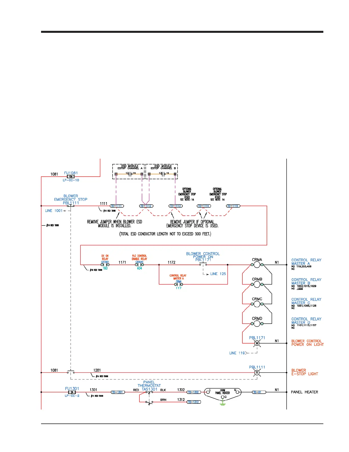
EMERGENCY STOP
Reference Figure 2-2
The Emergency Stop circuit in the blower control pan-
el energizes the Master Control Relay, which provides
power to PLC outputs that control actuators, heaters,
motor starters, valves, etc. The Master Control Relay
may be energized by pressing the “Control Power On”
illuminated pushbutton on the door of the blower con-
trol panel. When the Master Control Relay is energized,
the “Control Power On” pushbutton will illuminate. The
following conditions must be satisfi ed to energize the
Master Control Relay:
• Emergency Stop pushbutton on the door of the blow-
er control panel must be pulled out.
• Any additional Emergency stops or safety devices
tied in to the Emergency Stop circuit must be reset.
• The blower PLC must be booted up and operational.
• The 24-volt DC power supplies in the blower control
panel must be powered up and OK.
SUPPLEMENTAL BLOWER MOTOR PROTECTION
In the event that the controller detects a blower motor
running when it is not being commanded to run by the
controller, the controller will energize a blower-specifi c
supplemental shutdown output. This output can be
used to control a shunt trip, under-voltage release, iso-
lation contactor, or other safety power removal device.
Figure 2-2. Control Panel Master Power and Emergency Stop Electrical Circuit



 To Next Page