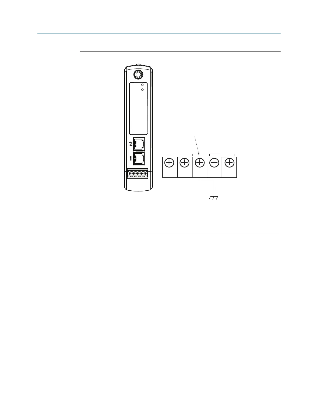
Figure 3-5: Emerson Smart Wireless Gateway 1410 Terminal Block
A
5-screw terminal block
B
24 VDC (nominal) power input
C
Serial Modbus
®
Ethernet connections should use Cat5e shielded cable to connect to an Ethernet hub,
switch, or router. The maximum cable length should not exceed 328-ft. (100 m).
3.4.3
RS-485
The Gateway can be ordered with an optional RS-485 (serial) connection (Figure 3-6).
Modbus terminals are labeled A and B on the wiring diagram. This connection is used to
communicate Modbus RTU on an RS-485 data bus.
Use 18 AWG single twisted shielded pair wiring to connect the Gateway to the RS-485 data
bus. The total bus length should not exceed 4000-ft. (1220 m). Connect the Tx - (negative,
receive) wire to terminal A and the Rx + (positive, transmit) wire to terminal B. The wiring
shield should be trimmed close and insulated from touching the Gateway enclosure or
other terminations.
If the existing data bus uses a 4-wire Full Duplex configuration, see Figure 3-6 to convert to
a 2-wire Half Duplex configuration.
Installation Reference Manual
September 2020 00809-0200-4410
22 Emerson.com/Rosemount

 Loading...

