Figure 3-6: Convert from Full to Half Duplex
3.4.4 Terminating resistors
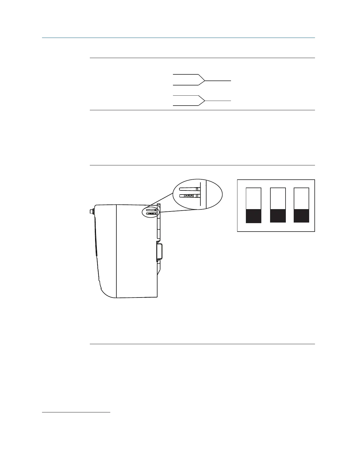
Three DIP switches are provided to enable various terminating resistors to the RS-485 data
bus. The switches are found inside the electronics housing, located behind an access slot
on the upper right side. The switches number bottom to top 1 through 3 and the upward
position is ON.
Figure 3-7: RS-485 Resistor DIP Switches
(1)
A
470 Ω pull-up resistor
B
120 Ω terminating resistor
C
470 Ω pull-down resistor
Switches 1 and 3 are connected to pull-up and pull down resistors. Switch 1 is for the Tx (A)
line and Switch 3 is for the Rx (B) line. These 470 ohm resistors are used to prevent noise
from being interpreted as valid communications during periods when no actual
communications are occurring. Only one set of pull-up and pull-down resistors should be
active on the RS-485 data bus at time.
Switch 2 is connected to a 120 ohm terminating resistor. This resistor is used to dampen
signal reflections on long cable runs. RS-485 specifications indicate that the data bus
(1)
Use a sharp non metal tool to switch between resistor options.
Reference Manual Installation
00809-0200-4410 September 2020
Emerson.com/Rosemount 23

 Loading...

