should be terminated at both ends (Figure 3-8). However termination should only be used
with high data rates (above 115 kbps) and long cable runs.
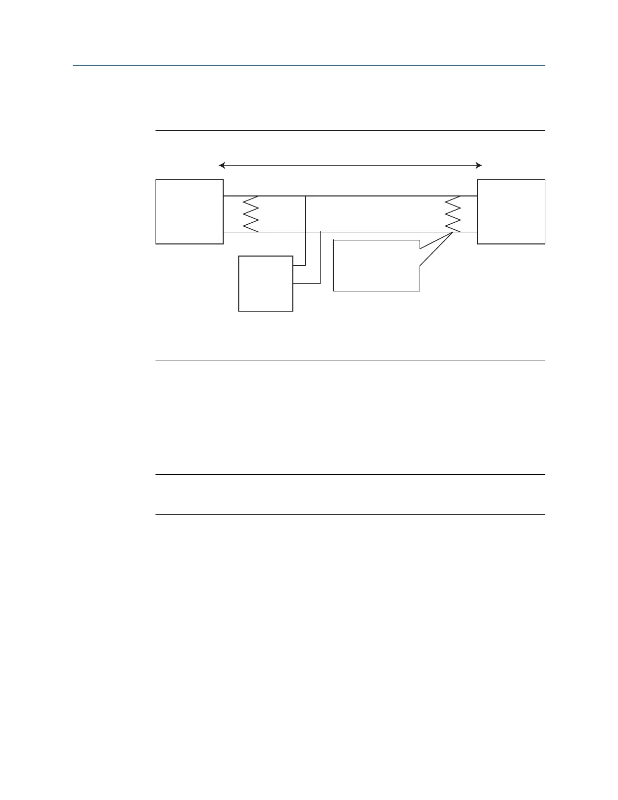
Figure 3-8: Typical Half Duplex (2-wire) Network
Up to 4000 ft. (1220 m)
Device 1
A
B
Terminators required
only for high data
rates and long cable
runs
Device N
(up to 32
possible)
Device 2
A
Tx line
B
Rx line
3.4.5 Power
The Gateway is designed to be powered by 24 VDC (nominal) Class 2 supply and requires
250 mA of current. The positive and negative connections are depicted on the diagram
shown in Figure 3-6.
The wiring should include an external power shut-off switch or circuit breaker located near
the Gateway.
Note
Using an uninterruptible power supply is recommended to ensure availability should there
be a loss of power.
Installation Reference Manual
September 2020 00809-0200-4410
24 Emerson.com/Rosemount

 Loading...

