8
REFRIGERANT PIPING
Tubing specifi cations
System supports refrigerant runs to internal. See Table 2,
Page 8. Units furnished with sweat connections, equipped
with refrigerant valves and Schrader fi ttings for charging
and taking pressure readings.
NOTICE
Install fi lter drier in liquid line at outdoor unit on all
models.
Table 2 - S1CV/S1HV Tubing Specifi cations
Model
Max.
Length
Equivalent
Feet
Max.
Lift
Max.
Trap
Height
Liquid
Line
Suction
Line
“H” “P” O.D. O.D.
09
100’
(30 m)
35’
(11 m)
20’
(6 m)
1/4" 1/2"
12 1/4" 1/2"
18 3/8" * 5/8"
24 3/8" * 5/8"
*Install 3/4” to 5/8” Bushing @ Air Handler
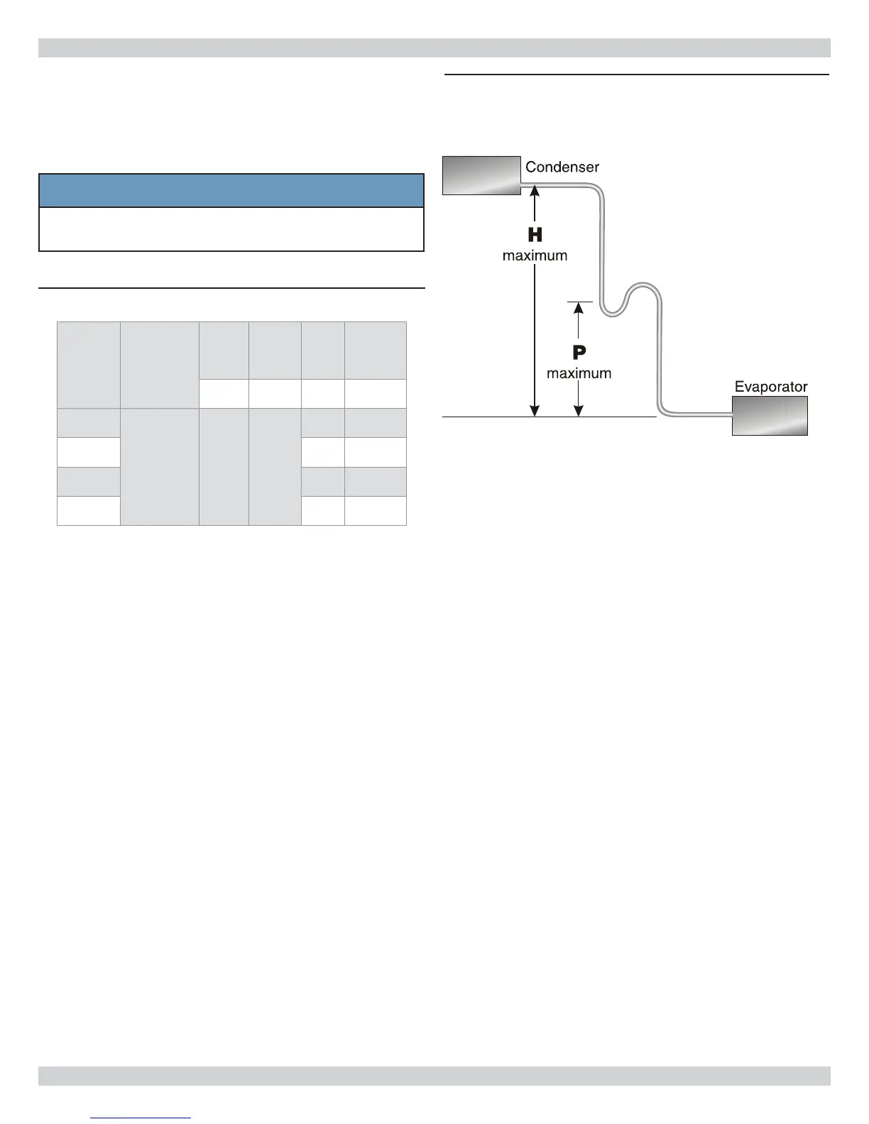
P-Trap Installation
• Recommend a P-trap when suction riser P is equal to
or greater than that shown in Figure 3 and Table 2 .
• Condenser installed above air handler, P-trap is
required. Facilitates return of oil back to compressor.
Locate trap at midpoint of rise
• Fabricate P-trap using 2 street elbows and 2 regular
elbows.
Or
• Purchase prefabricated trap from wholesaler or
distributor. Trap should be shallow as with 3 elbow
confi guration.
• Each elbow is approximately two (2) equivalent feet.
• One P-trap is equal to approximately 12 equivalent
feet.
• P-traps are not required at foot of hot gas risers due to
increased oil fl ow at higher temperatures.
Figure 3 - P-Trap Placement
(See Table 2 for Dimensions H & P)