12
ELECTRICAL WIRING
Site Preparation For Wiring
Electrical wiring must be in accordance with all electrical
codes. In absence of such requirements to the National
Electrical Code (NEC).
WARNING
Electrical shock hazard. Turn OFF electrical power
supply before making electrical connections. Failure
to do so could result in death or serious injury.
!
1.
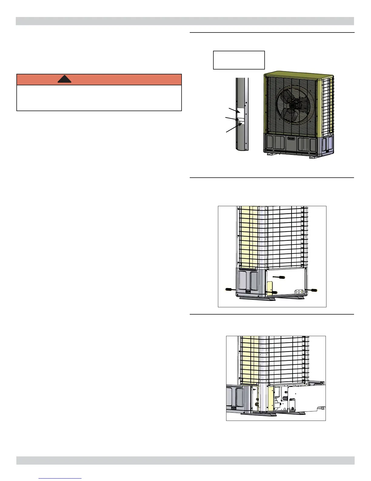
Refer to unit rating plate for voltage, minimum circuit
ampacity and over current protection requirements.
See Figure 11, Page 12.
2.
Use HACR type breakers or time delay fuses. Select
wire size according to ampacity rating.
3.
Electrical connections and wiring diagram see
Figure 12, Page 12 .
A. Remove screws on panel covering electrical box.
Box is located on back side of unit and is denoted
with electrical connections.
B. Remove back panel to access high/low electrical
connections and wire diagram.
C. Add water-tight strain relief fi tting to high volt side
before wiring. Split grommet fi tting factory installed
in low volt side. See Figure 15, Page 13 .
4.
Power runs to weather proof disconnect box within 3
feet of unit.
5.
From disconnect box run power through 7/8” hole on
back of unit and into electrical box. See Figure 15,
Page 13 .
6.
Run wires to high volt terminal strip in control box
and attach L1 and L2 connections. Run green wire to
ground lug.
7.
Check wiring diagram for required number of low
voltage wires to run between indoor and outdoor
sections. (4 conductor - A/C & 6 conductor - HP)
8.
Connect 24 volt wiring matching terminal to terminal.
Refer to the wiring diagram on the inside panel of
condenser, and wiring diagram on indoor unit. Low
volt interconnect should be at least 18 awg. Figure 16,
Page 13.
9.
See Figure 16, Page 13 for completed wiring of S1CV
examples.
10.
Replace back panel.
11.
Fasten all remaining loose screws.
Rating
Plate
ETL
ARI
Rating Plate
Figure 11 - Rating Plate Location
Figure 12 - Remove Back Panel Screws
Figure 13 - Remove Back Panel