38
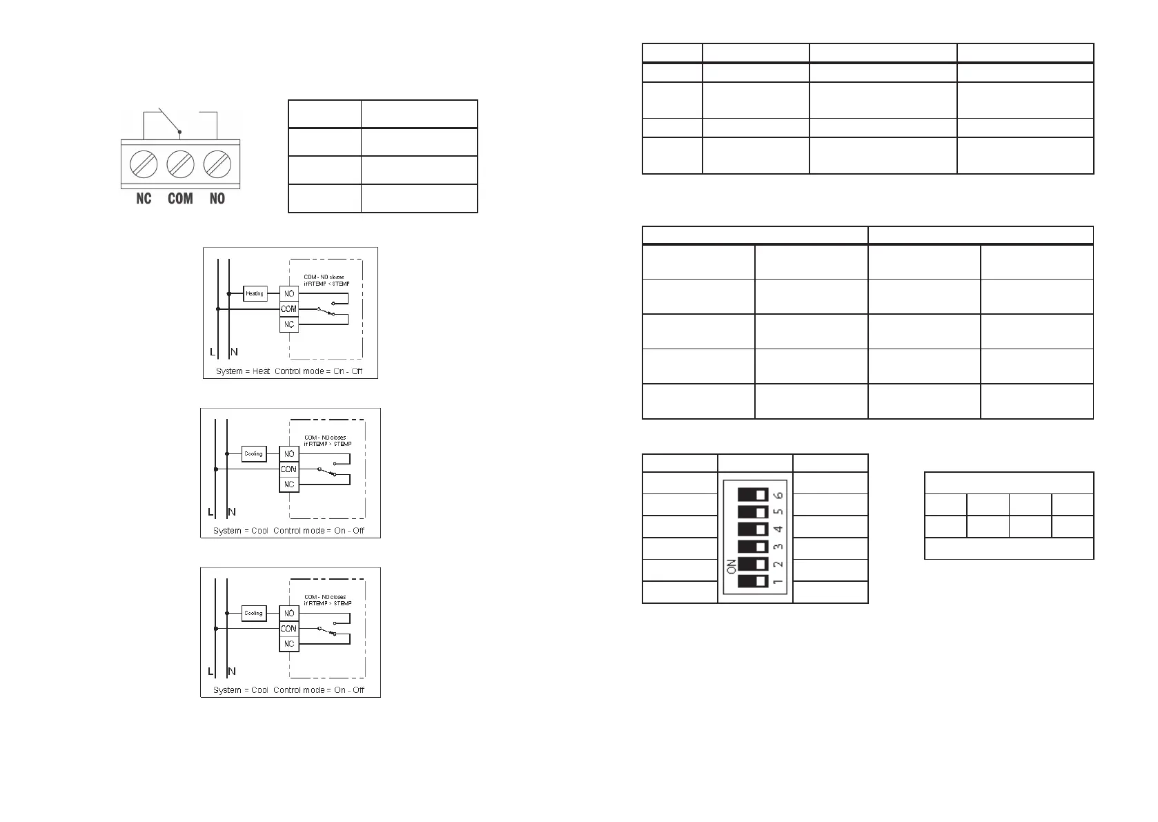
The terminals on PCB can be used to connect the power supply and
the controlled device.
Terminal Function
COM Common
NO Normal Open
NC Normal Close
•
Heating
•
Cooling:
•
Heating with PWM
Basic settings
The switches on PCB can be used to turn on or o of below functions.
39
Switch Function OFF ON
C/H Heat /cool system Heat (Default) Cool
PWM Control mode
ON-OFF
Control (Default)
PWM Control
7D/5-2D Programming day 5-2 days (Default) 7 days
F/C
Temperature
Scale
Celsius (Default) Fahrenheit
The switches SPAN1 and SPAN2 on PCB use to select the SPAN as per below table.
The factory default setting for all these functions are listed on above table.
Switch Control mode
SPAN2 SPAN1
ON-OFF
Control
PWM Control
OFF (Default) OFF (Default) 0.5 °C/ 10 °F
1 °C/ 20 °F,
300 seconds
OFF ON 1.0 °C/ 20 °F
2 °C/ 40 °F,
300 seconds
ON OFF 1.5 °C/ 30 °F
1 °C/ 20 °F,
300 seconds
ON ON 2.0 °C/ 40 °F
2 °C/ 40 °F,
300 seconds
DIP switch label
ON DIP Switch OFF
P 7d
P 5/2d Response
10
Î
1100
1 0 1010
°F °C Slow . . . Fast
PWM ON/OFF
Cool Heat
Precautions
This product is engineered to give you years of satisfactory service if you handle it
carefully. Here are a few precautions:
1. Please keep out of reach of children.
2. Do not clean the unit with abrasive or corrosive materials. They may scratch the
plastic parts and corrode the electronic circuit.
3. Do not subject the unit to excessive force, shock, dust, temperature or humidity, which may
result in malfunction, shorter electronic life span, damaged battery and distorted parts.