Installation
© 2017 EMP, Inc. 15
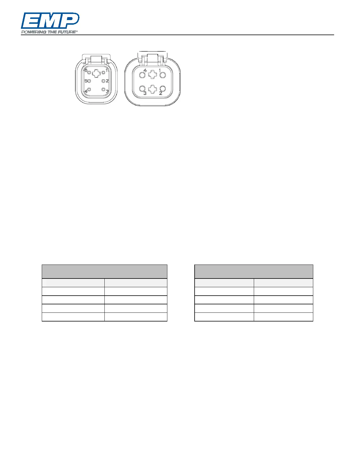
Connector Information
NOTE: These represent the controller connectors — not the mating harness connectors.
NOTE: Addressing and motor status message information can be found in Component Controller CAN
Communication, EMP document 9980001068.
NOTE: Ignition enable is a wake up signal sent to the controller to turn on. This is separate from the power
and ground and should be tied to a switched source and not tied to the component power.
The following notes apply to all connectors:
NOTE: All cavities in the mating connector must either be terminated or plugged to prevent moisture from
entering the controller.
NOTE: To operate the component, pin 4 (IGNITION ENABLE) must be connected +9 to 32vdc. This can be
wired directly to ignition, to a PLC output, through a manual switch or through a thermal switch. This line
will draw less than 10 mA. All switches used on this line can be sized based on this amperage requirement.
This input should be fused close to the source to protect the vehicle wiring.
Mating Connectors
The mating connectors and pins are available from EMP.
6 Pin Connector Deutsch Part Numbers
EMP Kit # 1370001077
4 Pin Connector Deutsch Part Numbers
EMP Kit # 1370001078
NOTE: If CAN or Serial TTL control is not used the 6 pin DTM connector must be blocked off to prevent
entry of water or dirt which will result in damage to the component. All pumps are shipped with this blocked
off connector. If lost or damaged, a block off plug, EMP P/N 3250001030 can be purchased.
2 – CAN SHIELD
3 – SERIAL GND
4 – SERIAL TX
5 – SERIAL RX
6 – CAN LO
1 – TEMP INPUT OR CAN ADDRESS
2 – GND
3 – BATT
4 – IGNITION ENABLE