Select User’s Manual
39
Specifications
Specifications
To Select Parameters for Programs
To Initiate Press Set button while device is on in the appropriate program option. Display will show
what Program is currently selected.
To Toggle Press the Set button again to toggle through the parameters.
To change Use the Channel 1 or Channel 2 Intensity buttons to change the parameters.
To Exit Press Mode button. Automatic exit will happen after 10 seconds and display the
Treatment Screen.
Data Retrieval Codes
SES
# of sessions (maximum 255)
ASL
Average session length (hours and tenths of hours)
HrS
Total hours in use
Channel 1
Actual average intensity
Channel 2
Actual average intensity
Battery Information
Supply Voltage Range
Low Voltage Indicator Threshold
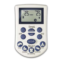
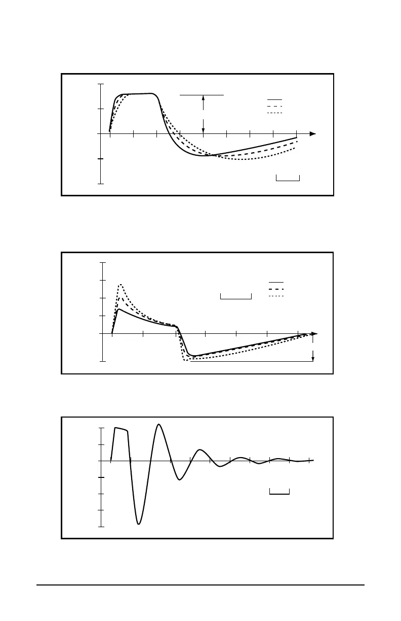
Waveforms shown are typical:
Voltage (V)
40
20
0
-20
-40
Pulse width
1k�
Vpp
500�
200�
Time
100�s
Figure A.
Standard measurement output voltage across purely resistive loads at
maximum High Output Intensity setting. Pulse duration and Vpp measured as shown
across a 1 K
Ω load.
Voltage (V)
40
20
0
-20
-40
1k�
+Vp
500�
200�
Time
100�s
Figure B.
Output voltage across AAMI loads at 50% of maximum High Output Intensity
setting. Output is nominally constant voltage for intensity settings of 20 (80µs) or greater.
Current (mA)
60
40
20
0
-25
1k�
-Ip
500�
200�
80
Time
100�s
Figure C.
Output current into AAMI loads at 50% of maximum High Output Intensity
setting. Negative phase (undershoot) is nominally constant current.
Voltage (V)
20
0
-20
-40
-80
40
200�s
-60
Figure D.
Output voltage across a 1MΩ resistive load at 50% of maximum High Output
Intensity setting.
user_manual_NEW_BH_edit_r5.indd 38-39 3/3/08 2:08:47 PM
2.26V d.c.
2.26V d.c minimum to 3.3V d.c. maximum