7/15 EmpirBus Connect-50 User manual Ver. 1.33
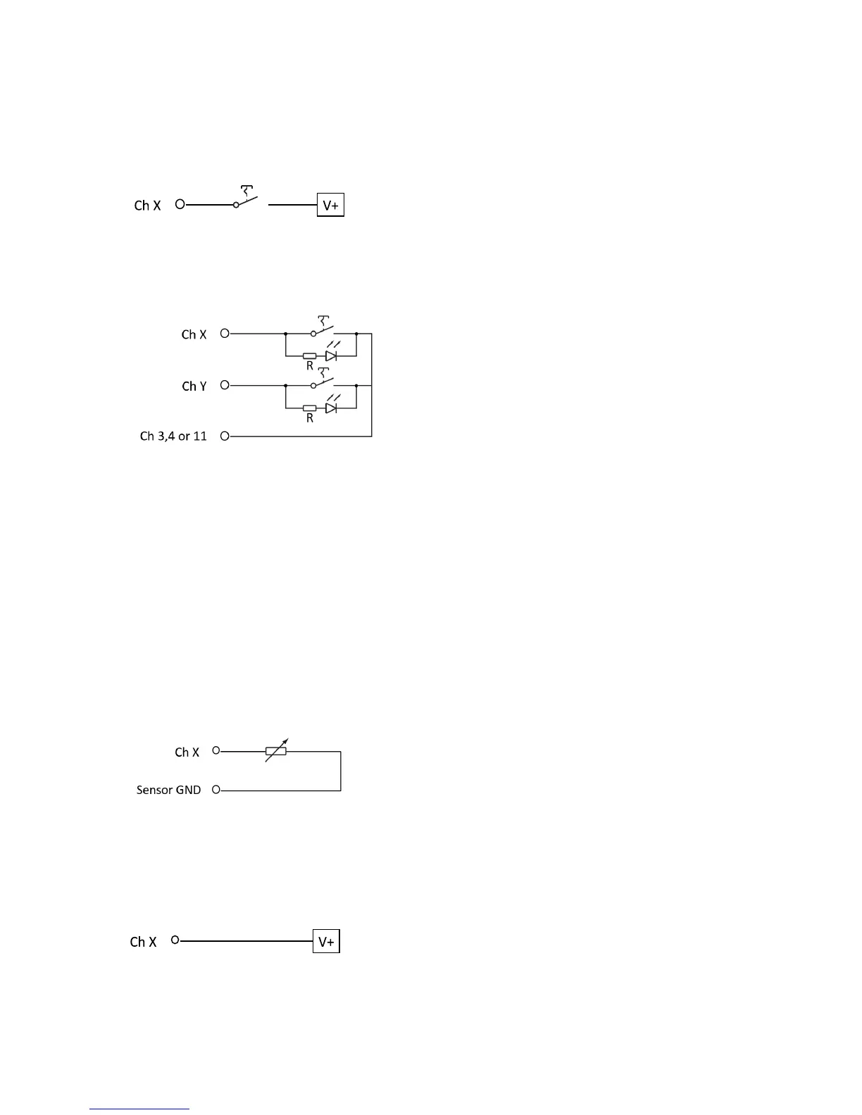
6.1.2!Digital!input!–!positive!!
Connect the switch between the source and the desired channel. See data sheet for measuring range
NOTE: The input signal source and the Connet-50 must have common ground.
6.1.3!Digital!input!–!common!line!
It is possible to have a switch and a LED indicator on the same channel using the circuit below. The
commonline channel then needs to be connected to channel 3, 4 or 11.
The value of the resistor R can be calculated using:
R = (Voltage supply – LED forward voltage) / 0.020A
LED forward voltage (Vf) = nominal 1.7 – 2.2 V
Example 12V system:
14.5V – 1.7V = 12.8V
12.8 / 0,020 = 640Ω minimum
(680Ω or higher recommended)
6.1.4!Analog!input!–!resistance!
Connect the resistive sensor directly between “Sensor GND” pin 32 and the desired channel.
6.1.5!Analog!input!–!voltage!
Connect the voltage source to the desired channel. See data sheet for measuring range. NOTE: The
input signal source and the Connect-50 must have common ground.
!
 Loading...