EmpirBus Connect-50 User manual Ver. 1.33 8/14
6.1.6!Analog!input!–!multi!switch!
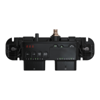
The circuit below enables four separate momentary switches to be connected to a single input
channel. Connect the circuit to “Sensor GND” pin 32 and the desired channel. Note: Multi switch
channel setting is only possible for momentary switches. Only one button can be pressed at a time.
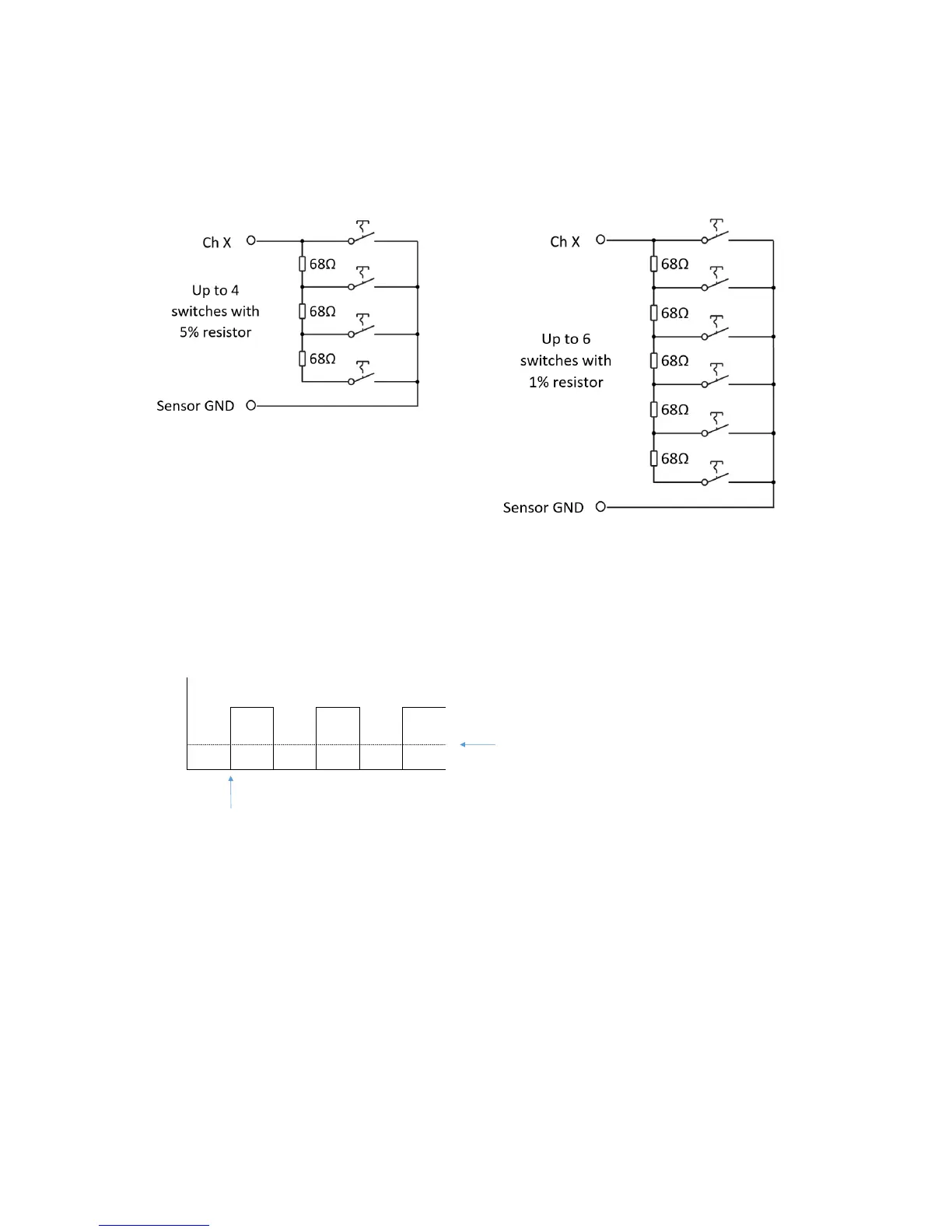
6.1.7!Frequency!input!-!digital!
Channel 6 and 22 could be configured to frequency input. Input signal is flank triggered at positive
flank with configurable thresholds level.
!
6.1.8!Signal!drive!-!output!
Input channel can be configured to drive up to 50mA plus or minus. This will be supplied via an
internal resistance, see below table for voltage drop.
 Loading...