5/15 EmpirBus NXT DCM User manual Ver 1.53
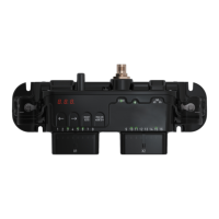
6.1.2!Digital!input!–!positive!!
Connect the switch directly between the source (V+) and the desired channel. NOTE: The input and
the DCM must have the same power supply.
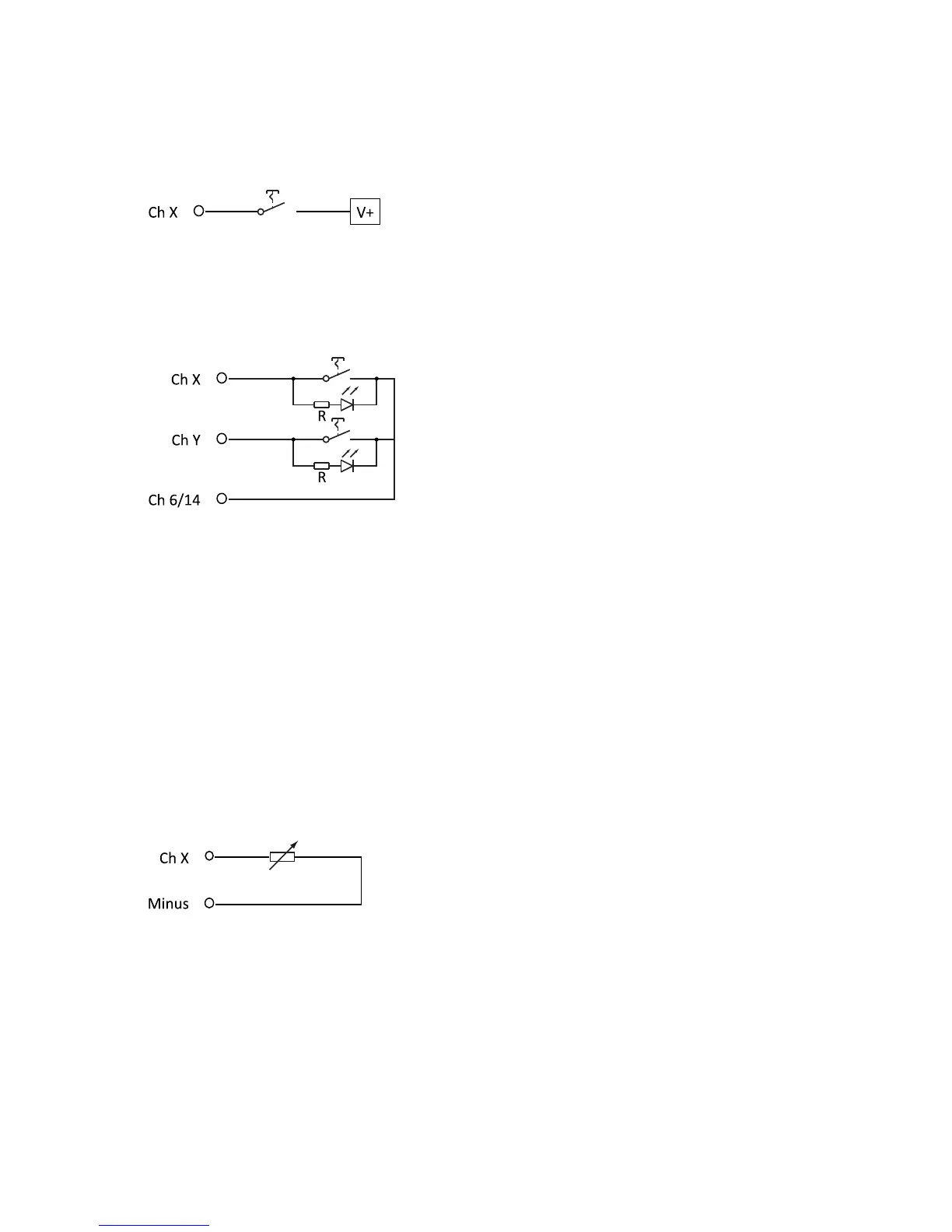
6.1.3!Digital!input!–!commonline!
It is possible to have a switch and a LED indicator on the same channel using the circuit below. The
commonline channel needs to be connected to a channel that can switch to minus, which is possible
on channel 6 or 14 on all DCM models.
The value of the resistor R can be calculated using:
R = (Voltage supply – LED forward voltage) / 0.020A
LED forward voltage (Vf) = nominal 1,7 – 2,2 V
Example 12V system:
14.5V – 1.7V = 12,8V
12.8 / 0,020 = 640Ω minimum
(680Ω or higher recommended)
Example 24V system:
29V – 1.7V = 27,3V
27.3V / ,.020 = 1365Ω minimum
(1500Ω or higher recommended)
6.1.4!Analog!input!–!resistance!
Connect the resistive sensor directly between minus and the desired channel.
!
 Loading...