EmpirBus NXT DCM User manual Ver 1.53 6/15
6.1.5!Analog!input!–!voltage!
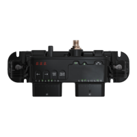
Connect the voltage source directly to the desired channel. See data sheet for measuring range.
NOTE: The input signal source and the DCM must have common ground.
If input signal source is powered by another power supply, a resistor must be connected in series to
the input. A 10kΩ resistor is recommended for this purpose. The programming must take this in
consideration. NOTE: The power supply for the input signal source and the DCM must have
common ground. (I.e. Both batteries must have common ground.)
Input value x (15kΩ / (15kΩ + R) = measured value
Example 12V system:
12V x (15kΩ / (15kΩ + 10kΩ) = 7,2V
Example 24V system:
24V x (15kΩ / (15kΩ + 10kΩ) = 14,4V
!
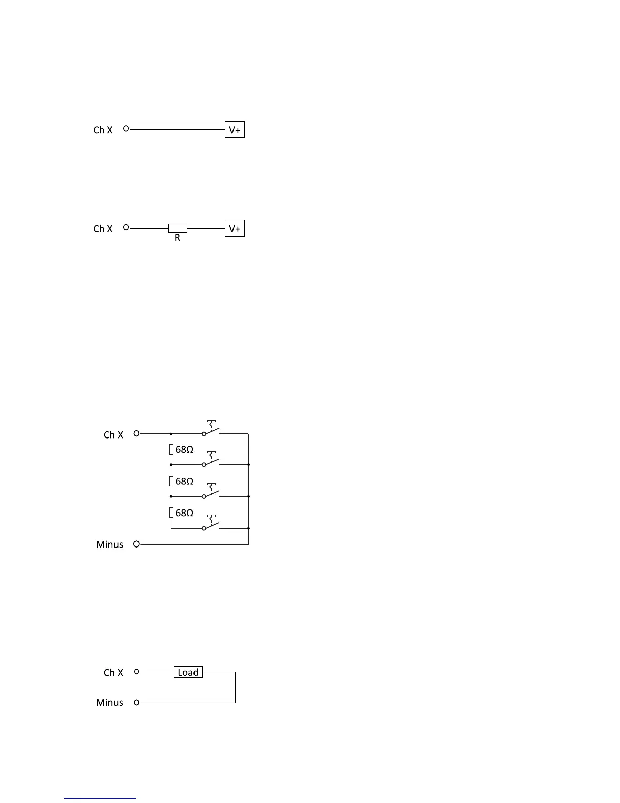
6.1.6!Analog!input!–!multi!switch!
The circuit below enables four separate momentary switches to be connected to a single input
channel. Note: Multi switch channel setting is only possible for momentary switches. Only one
button can be pressed at a time.
6.2!Outputs!
Depending on the model, certain channels can be configured to be outputs. See the table 9.1 for
model specification.
6.2.1!Digital!output!–!positive!
Connect the load directly between the desired channel and minus.
 Loading...